


51
6. Connect the two coolant hoses to the elbow fit-
tings of the crankcase and tighten the hose clamps;
then install the coolant hose and vent hose to the
cylinder head and secure with hose clamps.
IO045A
IO044A
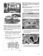
7. Install the throttle body assembly into the intake
flanges; then tighten the flange clamps securely.
IO043B
8. Place the oil tank into position and secure with the
four cap screws and lock nuts. Tighten securely;
then connect the low oil sensor harness connector
to the oil tank and the oil-injection hose from the
oil tank to the oil pump.
IO047A
IO039A
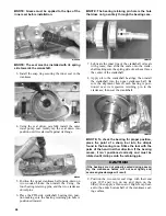
9. Connect the coolant hose (A) to the throttle body
assembly; then connect the gasline supply hose
(B) to the delivery pipe of the throttle body assem-
bly. Secure with the clamps.
745-867A
10. With the harness routed properly, connect the two
injector harness connectors (C) and the throttle
position sensor connector (D) to the throttle body
assembly.
11. Connect the five ignition/main harness connectors;
then install the harness cover and secure with
cable ties.
CAUTION
When installing the assembly, it is advisable to have
the flange clamps loose enough to slide forward from
the mounting location to avoid damaging the clamps.
A
55
D
C
B
Содержание 2014 SNO PRO 500
Страница 1: ...SNO PRO 500 ...
Страница 16: ...12 Wiring Diagram Hood Harness p n 1686 587 0744 201 ...
Страница 17: ...Wiring Diagram Ignition Main Harness p n 1686 628 0745 605 13 ...
Страница 18: ...14 NOTES ...
Страница 89: ......
Страница 90: ...Printed in U S A Trademarks of Arctic Cat Inc Thief River Falls MN 56701 p n 2259 778 ...