


88
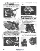
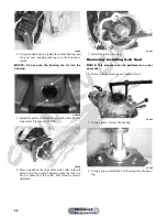
8. Remove the upper and lower ball joint cap screws
taking care not to strip the threads.
AF628D
9. Pull the steering knuckle away from the axle taking
care not to damage the seals as the axle clears the
knuckle.
KC314
10. Support the axle to not allow it to drop or hang.
11. Using the Slide Hammer Kit, remove the front axles.
KC289
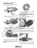
12. Remove the cap screws from the drive coupler
flange; then remove the upper and lower mounting
cap screws and remove the differential from the
frame.
KC291A
Disassembling Input Shaft
NOTE: This procedure can be performed on a rear
gear case; however, some components may vary
from model to model. The technician should use dis-
cretion and sound judgment.
1. Remove the cap screws securing the front drive actu-
ator and remove the actuator; then remove the cap
screws securing the pinion housing.
CD102
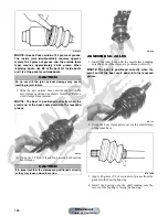
2. Using a rubber mallet, remove the housing. Account
for a gasket. Remove the fork, collar, and spring.
Note the location of all the components for assem-
bling purposes.
CD103
CAUTION
Apply pressure to hold the ball joint firmly in the knuckle
or the threads will be stripped when the retaining cap
screws are removed.
CAUTION
The axle must be supported. If the axle is allowed to
drop or hang, damage to the inner CV joint may occur.
Manual
Table of Contents


