


41
MD1261
28. In a crisscross pattern starting from the center and
working outward, tighten the cap screws (from step
27) to 8 ft-lb.
29. Adjust valve/tappet clearance (see Periodic Mainte-
nance).
30. Place the two tappet covers with O-rings into posi-
tion; then install and tighten the cap screws securely.
MD1264
31. Install the spark plug and tighten securely; then
install the timing inspection plug.
Left-Side Components
NOTE: For efficiency, it is preferable to remove and
disassemble only those components which need to
be addressed and to service only those components.
The technician should use discretion and sound
judgment.
NOTE: The engine/transmission does not have to
be removed from the frame for this procedure.
Removing Left-Side
Components
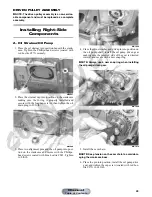
A. Cover/Stator Assembly
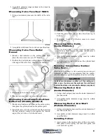
1. Remove the cap screws securing the outer magneto
cover and remove the cover.
2. Remove the left-side cover-to-crankcase mounting
cap screws noting the location of the 8 mm cap screw
with the washer near the middle of the left-side
cover. Keep the different-lengthed 6 mm cap screws
in order for installing purposes.
MD1186
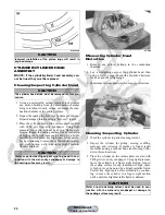
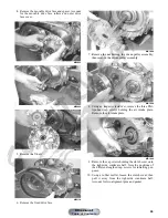
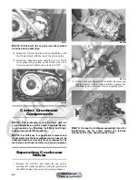
3. Using Crankcase Separator/Crankcase Remover and
the 6 mm adapter, remove the left-side cover w/sta-
tor assembly. Account for the two alignment pins
and the position of the shifter bracket for installing
purposes.
CC946
MD1188
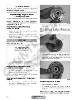
AT THIS POINT
To service any one specific component, only limited dis-
assembly of components may be necessary. Note the
AT THIS POINT information in each sub-section.
Manual
Table of Contents