


75
NOTE: If the battery voltage is 11.5 DC Volts or less,
some chargers may “cut off” and fail to charge. If this
occurs, connect a fully charged booster battery in
parallel (positive to positive and negative to negative)
for a short period of time with the charger connected.
After 10-15 minutes, disconnect the booster battery
leaving the charger connected and the charger
should continue to charge. If the charger “cuts off,”
replace the battery.
8. After charging the battery for the specified time,
remove the battery charger and allow the battery to
sit for 1-2 hours.
9. Connect the multimeter and test the battery voltage.
The meter should read 12.5 or more DC Volts. If the
voltage is as specified, the battery is ready for ser-
vice.
NOTE: If voltage in step 9 is below specifications,
charge the battery an additional 1-5 hours; then
retest. Recheck electrolyte level and the battery is
ready for service.
10. Place the battery in the battery compartment; then
coat the battery posts and cable ends with a light coat
of multi-purpose grease.
11. Connect the battery cables (positive cable first); then
install the battery hold-down.
RPM Limiter
NOTE: The ATV is equipped with a CDI that retards
ignition timing when maximum RPM is approached.
When the RPM limiter is activated, it could be misin-
terpreted as a high-speed misfire.
Testing Electrical
Components
All of the electrical tests should be made using the Fluke
Model 73 Multimeter or Fluke Model 77 Multimeter and
when testing peak voltage, the Peak Voltage Reading
Adapter must be used. If any other type of meter is used,
readings may vary due to internal circuitry. When trou-
bleshooting a specific component, always verify first that
the fuse(s) are good, that the bulb(s) are good, that the
connections are clean and tight, that the battery is fully
charged, and that all appropriate switches are activated.
NOTE: For absolute accuracy, all tests should be
made at room temperature of 68° F.
Accessory Receptacle/
Connector
NOTE: This test procedure is for either the recepta-
cle or the connector.
VOLTAGE
1. Turn the ignition switch to the ON position; then set
the meter selector to the DC Voltage position.
2. Connect the red tester lead to the red wire; then con-
nect the black tester lead to ground.
3. The meter must show battery voltage.
NOTE: If the meter shows no battery voltage, trou-
bleshoot the battery, fuse, receptacle, connector, or
the main wiring harness.
Brakelight Switch
(Pressure)
The brakelight switch is located on the top of the auxil-
iary brake master cylinder and is pressure activated by
the hand brake or the auxiliary brake pedal. This switch
also activates the start-in-gear (SIG) relay in the power
distribution module (PDM).
NOTE: The ignition switch must be in the ON posi-
tion.
VOLTAGE
(Wiring Harness Side)
1. Set the meter selector to the DC Voltage position.
2. Connect the red tester to the brown/black wire; then
connect the black tester lead to ground.
3. The meter must show battery voltage.
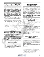
Battery Charging Chart (Constant-Current Charger)
Battery Voltage
(DC)
Charge
State
Charge Time Required
(at 1.5-2.0 Amps)
12.5 or more
100%
None
12.2-12.4
75%-99%
3-6 hours
12.0-12.2
50%-74%
5-11 hours
11.0-11.9
25%-49%
13 hours (minimum)
11.5 or less
0-24%
20 hours (minimum)
CAUTION
Before installing the battery, make sure the ignition
switch is in the OFF position.
CAUTION
Connecting cables in reverse (positive to negative and
negative to positive) can cause serious damage to the
electrical system.
Manual
Table of Contents


