

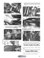


81
Gear Position Switch
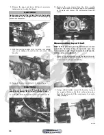
The gear position switch connector is located on the right
side of the engine over the V-belt housing.
KC227A
To troubleshoot the switch, use the following procedure.
1. Disconnect the gear position switch from the main
harness at the connector; then connect the black tes-
ter lead to a suitable ground.
2. Select the OHMS position on the tester and connect
the red tester lead to the lavender/red wire; then
move the shift lever to the R (reverse) position. The
meter must read less than 1 ohm.
3. Move the red tester lead and shift lever in turn to the
light green/red wire and N (neutral) position, white/
black wire and H (high) position, and white/red wire
and L (low) position. The meter must read less then 1
ohm in all positions. If not, the shift linkage must be
adjusted (see Periodic Maintenance) or the switch
must be replaced.
Stator Coil
VOLTAGE
(AC Generator - Regulated Output)
1. Set the meter selector to the DC Voltage position.
2. Connect the red tester lead to the positive battery
post; then connect the black tester lead to the nega-
tive battery post.
3. With the engine running at a constant 3000 RPM
(with the headlights on), the meter must show 14-
15.5 DC volts.
NOTE: If voltage is lower than specified, test charg-
ing coil - no load.
VOLTAGE (Charging Coil - No Load)
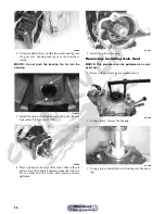
The connector is the black three-pin one on the right side
of the engine just above the starter motor.
NOTE: Test the engine-side of the connector.
1. Set the meter selector to the AC Voltage position.
2. Test between the three black wires for a total of three
tests.
3. With the engine running at the specified RPM, all
wire tests must show 60 AC volts.
NOTE: If both charging coil tests failed, check all
connections, etc., and test again. If no voltage is
present, replace the stator assembly.
RESISTANCE (Charging Coil)
1. Set the meter selector to OHMS position.
2. Test between the three black wires for a total of three
tests.
3. The meter reading must be within specification.
RESISTANCE (Trigger Coil)
1. Disconnect the gray four-pin connector on the right
side of the engine just above the starter motor.
2. Set the meter selector to the OHMS position.
3. Connect the red tester lead to the green wire; then
connect the black tester lead to the blue wire. The
meter reading must be within specification.
PEAK VOLTAGE
NOTE: All of the peak voltage tests should be made
using the Fluke Model 73 Multimeter or Fluke Model
77 Multimeter with Peak Voltage Reading Adapter. If
any other type of tester is used, readings may vary
due to internal circuitry.
NOTE: The battery must be at full charge for this test.
Trigger Coil
1. Set the meter selector to the DC Voltage position.
2. Connect the red tester lead to the green wire; then
connect the black tester lead to the blue wire.
3. Crank the engine over using the electric starter.
4. The meter reading must be within specification.
Starter Relay
1. Remove the seat; then using the multimeter set to the
DC Voltage position, check the relay as follows.
CAUTION
Do not run the engine at high RPM for more than 10 sec-
onds.
CAUTION
Do not run the engine at high RPM for more than 10 sec-
onds.
Manual
Table of Contents


