80
SP366
6. Install the rear wheels and tighten the nuts to 30 ft-lb;
then remove the support stand and lower the ATV to
the floor.
7. Check chain tension (see Periodic Maintenance/
Tune-Up - Drive Chain) and make sure the brake
functions normally.
Front A-Arms
REMOVING
1. Secure the ATV on a support stand to elevate the
front wheels; then remove the wheel on the side
being serviced.
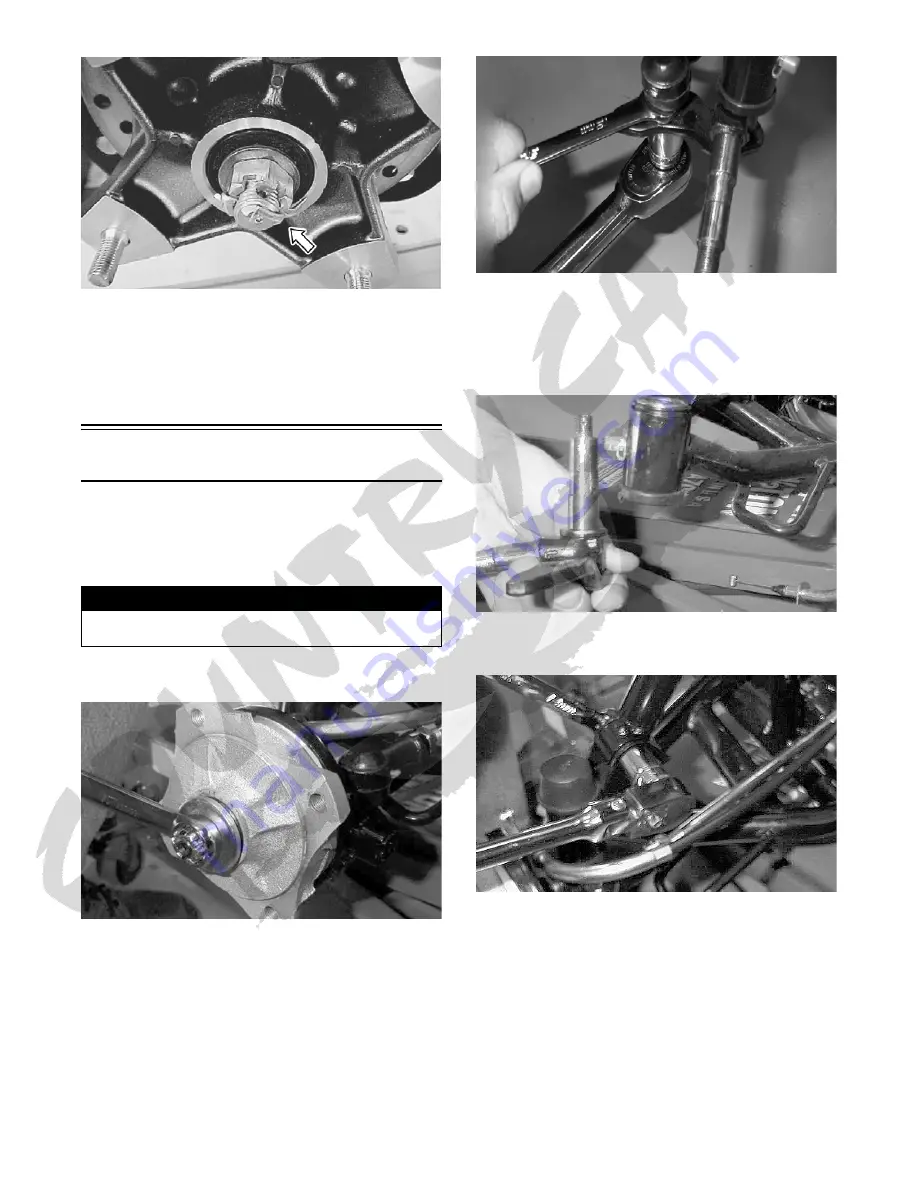
2. Remove the cotter pin, castle nut, and washer; then
remove the hub assembly.
MD2133
3. Slide brake backing plate assembly off the spindle
shaft and secure it out of the way.
4. Remove the cotter pin from the outer tie rod end;
then while holding the flat on the tie rod end, remove
the castle nut.
MD2428
5. Remove the tie rod end from the steering knuckle.
6. Remove the rubber spindle pin boot; then remove the
cotter pin and flanged castle nut from the spindle pin.
Lower the steering knuckle assembly from the A-
arm.
MD2113
7. Remove the cap screw and self-locking nut securing
the shock absorber to the A-arm.
MD2132
8. Remove the cap screws and self-locking nuts secur-
ing the A-arm to the frame.
! WARNING
Make sure the ATV is solidly supported on the support
stand to avoid injury.


