


9. Testing
It is recommended that the unit is tested prior to substation energizing. Testing is carried out by
simulating an arc light for each sensor and verifying that the unit tripped and that the correct indicator
LED turned on.
A high-quality camera flash (Canon Speedlite 430EX or equivalent) is used to simulate arc light. You
can use a flashlight (Mini Maglite 2 CELL AAA or equivalent) to test non-latched signals and the CBFP
function. Before testing please check that the equipment used has a fully charged battery.
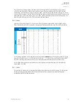
9.1. Testing the light-only mode
1. Check that the DIP switch settings are positioned according to your application.
2. Activate the camera flash within 30 cm (12 inches) of the sensor that is being tested.
3. Verify that the indicator LED of the corresponding sensor channel is lit.
4. Verify the activation(s) of the relay output(s) by checking the circuit breaker's status, or by
monitoring the trip contact's status. The circuit breaker should open, or the contacts operate.
Please note that you achieve the best test results when you operate the circuit breaker while
testing.
5. Verify that the indicator LED(s) of the corresponding relay output(s) is lit.
6. If you are using the BO1 binary output and/or one or both of the high-speed outputs, verify
their signal activation either through the status change of the relevant input, or by measuring
the signal output voltage. Please note that BO1 is of the non-latched type.
7. If you are using the BO1 binary output and/or one or both of the high-speed outputs, also
verify that their corresponding LED is lit.
8. Press the SET
SET push button to reset all indications and latches.
9. If you are using the BI2 binary input as the master trip, activate it and verify that the trip has
occurred by repeating the steps 4 and 5.
10. Press the SET
SET push button to reset all indications and latches.
11. Repeat the steps 1 through 10 for all sensors.
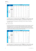
9.2. Testing the light and current mode
1. Check that the DIP switch settings are positioned according to your application.
2. Activate the following two things simultaneously: the camera flash within 30 cm (12 inches) of
the sensor unit that is being tested, and the BI1 binary input used for the overcurrent
condition (I>).
3. Verify that the indicator LED of the corresponding sensor channel is lit.
4. Verify that the indicator LED of the BI1 binary input is lit.
5. Verify the activation(s) of the relay output(s) by checking the circuit breaker's status, or by
monitoring the trip contact's status. The circuit breaker should open, or the contacts operate.
Please note that you achieve the best test results when you operate the circuit breaker while
testing.
6. Verify that the indicator LED(s) of the corresponding relay output(s) is lit.
7. If you are using the BO1 binary output or a high-speed output (HSO1 and/or HSO2), verify
the signal activation either through the status change of the relevant input, or by measuring
the signal output voltage.
8. If you are using the BO1 binary output or a high-speed output (HSO1 and/or HSO2), also
verify that the corresponding LED is lit. Please note that BO1 is of the non-latched type.
9. If you are using the BO2 binary input, verify its correct operations by activating the input.
10. Activate the camera flash within 30 cm (12 inches) of the point sensor unit but do not
activate the binary input used for the overcurrent condition (I>).
11. Verify that no trip has occured and only the indicator LED of the sensor activation is lit.
A
AQ
Q-103L
-103LV
V
Instruction manual
Version: 1.00
© Arcteq Relays Ltd
34