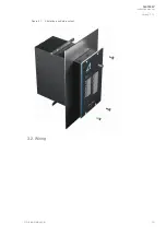


4. Operation and configuration
4.1. LED indicator functions
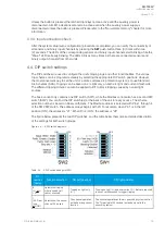
Both variants of the AQ-103LV unit have twenty-five (25) indication LEDs. Apart from the “Power” and
“Error” LEDs, the user can write their own identifications for each of the remaining LEDs on the text
insert sheet located in the transparent pockets next to the LEDs. The LEDs are on the unit’s front panel
to allow for a clear view without a separate need to open doors.
When the unit is powered up, it performs an LED test. All LEDs are turned on for two seconds and then
turned off. Only the blue "Power" LED stays on.
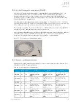
When the unit operates normally, only the blue "Power" LED is lit.
The LEDs of inactive sensors are off. If an arc sensor is activated for longer than 1.5 ms, its
corresponding LED turns on. The activation function of the sensor LEDs is latched when the LED's light
is not blinking.
If there is a loose sensor wire or if the self-supervision function detects a configuration mismatch (that
is, a new sensor has been attached but the auto-configuration system setup has not been run), the
corresponding LED starts flashing and the "Error" LED activates.
The binary I/O LEDs indicate the status of the input and output lines. If any of the lines become active
for longer than 1.5 ms, the corresponding LED turns on (that is, they become latched). This also
happens when a trip situation occurs. The trip outputs are controlled with DIP switch settings. All
activation and trip indication LEDs are latched, even if the DIP switch settings are in the non-latched
mode.
All LED indications are stored in the non-volatile memory (EPROM) to help identify the necessary trip
information if auxiliary power is lost. When the unit is re-powered after a power supply loss, the front
panel shows the status of all LEDs.
You can clear the LEDs by pushing the SET
SET button.
4.2. LED operations guide
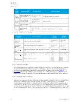
The table below describes the function of each indicator LED in detail (includes both variants).
Table. 4.2. - 1. LED operations of AQ-103LV (both variants).
LED
name
(color)
Off
Steady light
Blinking
Action if abnormal
POWER
(blue)
The auxiliary
power supply
is
disconnected.
The auxiliary power supply is
connected.
N/A
Check the power supply.
ERROR
(red)
The system is
healthy.
A system failure has occured.
A configuration mismatch has
been detected. Protection is
partially operational.
Verify the system condition
(see the "System self-
supervision" and
"Troubleshooting" chapters).
T1–T4
(red)
Normal
status.
The trip relay has activated.
N/A
Check what caused the trip,
clear the fault, and reset the
indicator LEDs with the push-
button.
A
AQ
Q-103L
-103LV
V
Instruction manual
Version: 1.00
© Arcteq Relays Ltd
16