

S5 can be configured to function as a fiber optic loop sensor channel or as a control for the arc
quenching system. The function of S5 in controlled with the SW1 DIP switch (please refer to the “DIP
switch settings” chapter for more information). When S5 is configured as a fiber optic loop sensor
channel, one end of the sensor is connected to the unit’s transceiver (Tx) terminal and the other to the
receiver (Rx) terminal. This sensor loop is then continuously monitored by a 60-μs test light pulse that
travels through the loop. If a discontinuity is detected, the unit goes into Error mode and activates the
“Error” LED and the SF relay output.
Alternatively, S5 can be configured to control the arc quenching system. Similarly, the unit sends a
continuous light pulse to the arc quenching system for self-supervision purposes.
For more information on sensors, please refer to the “Arc sensors” chapter as well as to the AQ-0x
instruction booklet which can be found on Arcteq's website (
https://www.arcteq.fi/downloads/
).
8.2.2. Binary inputs
The unit contains two (2) binary inputs, BI1 and BI2.
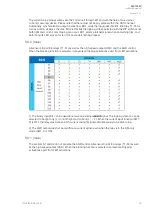
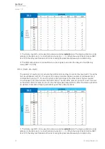
The function of the binary inputs is selected with the "SW1" DIP switch according to the logic scheme
used (for more information, please refer to the “DIP switch settings” chapter). Typically, the binary
inputs are used for receiving arc light information from AQ-101, AQ-102 and AQ-103 units as well as
for receiving overcurrent information from AQ-110 units.
The binary inputs are activated when a connected DC signal hits the 18…265 V DC voltage range. The
activation takes place at 15 V at the earliest, and the channel endures up to 265 V DC.
8.3. Auxiliary voltage
The auxiliary power supply voltage is 92….265 V AC/DC. Alternatively, the optional auxiliary power
supply can be of 18…72 V DC. This choice must be specified when ordering.
A
AQ
Q-103L
-103LV
V
Instruction manual
Version: 1.00
33
© Arcteq Relays Ltd