•
GND:
Ground terminal (1 ea.).
•
Relay Contacts:
Three terminals, marked NC, COM and NO
(Normally Closed, Common, Normally Open).
Conditions are
when relay is de-energized (clock powered OFF). The information
below gives the contact condition for two states: (1) Fault, or
Power OFF, and (2) No Fault, or Power ON.
1. Fault, or Power Off – COM to NC shorted,
COM to NO open.
2. No Fault and Power ON – COM to NC open,
COM to NO shorted.
•
DIP Switch Settings:
use the S1 DIP switches to configure
COM1, RS-232 port parameters. This port cannot be configured
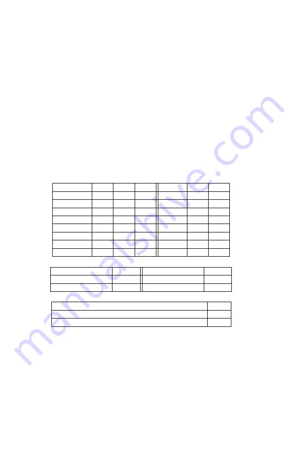
through the serial port like COM2. Table 2.1 covers the settings
for each switch (e.g. “Sw1"). * Default Settings.
Baud Rate
Sw1
Sw2
Sw3
Parity
Sw4
Sw5
1200
ON
OFF
ON
ODD
ON
OFF
2400
ON
ON
OFF
EVEN
OFF
ON
4800
ON
ON
ON
NONE*
OFF
OFF
9600*
OFF
OFF
OFF
–
–
–
19200
OFF
OFF
ON
–
–
–
38400
OFF
ON
OFF
–
–
–
57600
OFF
ON
ON
–
–
–
115200
ON
OFF
OFF
–
–
–
Data Bits
Sw6
Stop Bits
Sw7
7
ON
1*
OFF
8*
OFF
2
ON
COM1 Connector Select
Sw8
Terminal Lug Header*
OFF
Programming Port, RJ11
ON
Table 2.1: COM1 Dip Switches (*Factory default)
Ground Connection
Connect the GND terminal on the left terminal block (see Figure 2.2) to
one or more wires of the multi-conductor cabling that are connected to
a station ground.
14


