28
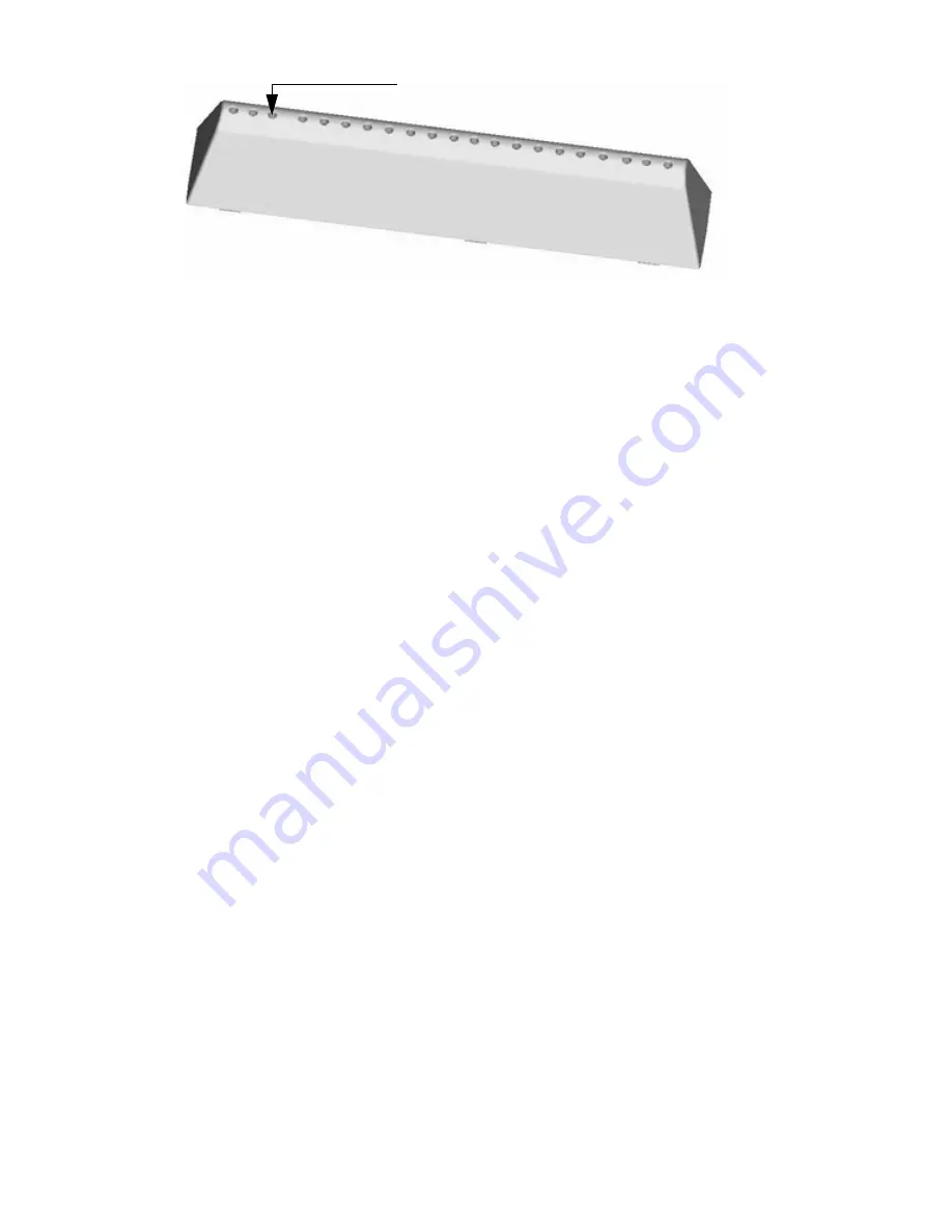
S Inner Drum Lifter
1. Insert a small screwdriver onto the 3rd lifter hole from the front of the drum.
This will depress the drum flap securing the lifter.
2. Slide the lifter to the front of the drum and remove.
3. Before refitting, lift the drum locking tab 3 mm above the drum surface.
4. Offer the lifter to the holes in the drum, slide lifter to the back of the drum until a click is heard as
the lifter is locked into place.
T
Drum Assembly
Note: This sealed drum assembly cannot be split to remove or repair the inner drum,
bearing support or bearings.
It must be replaced as a complete unit.
External components such as weights, bolts and hoses, motor and belt etc. will need to
be transferred from the faulty drum assembly.
1. Remove the table top (A).
2. Remove the top balance weight (Mb).
3. Remove the dispenser drawer (C).
4. Remove the console panel (D).
5. Remove the dispenser (Q).
6. Remove the front panel (J).
7. Remove the lower balance weight (Ma).
8. Remove the lower rear access panel (B).
9. Disconnect heater / thermistor wiring and release the wiring harness from the drum clips.
10. Detach the drum from the damper units by removing the two plastic pegs using special
tool Part No. 5600198.
11. Remove the sump hose fixing clip and detach the sump hose from the sump chamber.
12. Unclip any wiring retained within the integral clip on the spring bearing keeper plates.
13. Gently lever out the spring bearing keeper plates with a small flat bladed screwdriver.
14. Unhook springs from the cabinet top rail bearings.
15. Carefully lift the drum assembly out of the cabinet whilst supporting the drum.
3rd hole from the front


