aquabrass.com
31
last revision: 5/24/2017
Trims /
Plaques décoratives
#S21, #R21
9
10
11
12
8
7
6
2
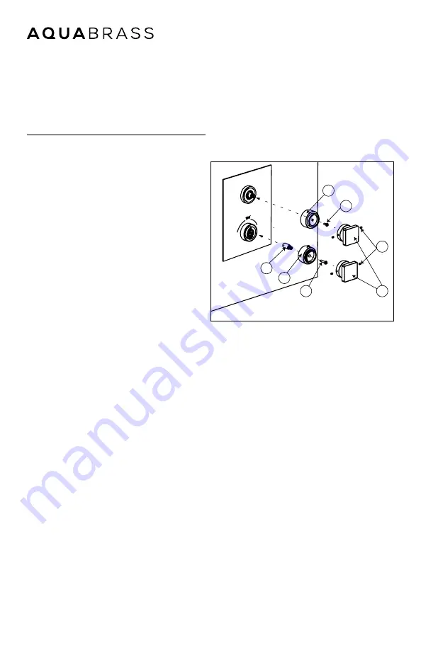
Installing The Handles
Installation des poignées
Fig.3
Insert the thermo broach extension (6) onto
the thermo cartridge broach. Afterwards, in-
sert the thermo handle adapter (7) onto the
thermo broach extension (6). Make sure the
temperature limit stopper button is aligned
with the 100˚ F mark on the trim (5) (fig.3).
Secure the thermo handle adapter with sup-
plied screw (8). Insert handle (9) and secure it
with the 2 supplied set screws (10) .
Insert the diverter (volume control) handle
adapter (11) onto the shut-off valve broach.
Secure it with supplied setscrew (11). Install
the handle (9) onto the diverter handle
adapter and secure it with 2 supplied set
screws (10).
Insérer la rallonge de la cartouche ther-
mostatique 6) sur la cartouche thermo-
statique. Ensuite, insérer l’adaptateur pour
la poignée thermostatique (7) sur la tête
de la rallonge (6) . Assurez-vous que le
bouton du limitateur de température soit
aligné avec la marque de 100˚F / 38˚C
inscrite sur la plaque (5) (Fig.3). Fixer ensuite
l’adaptateur (7) avec la vis (8) fournie.
Insérer la poignée (9) sur l’adaptateur et la
fixer avec les 2 vis de retenues (10) fournies.
Insérer l’adaptateur pour la poignée du
déviateur (contrôle de volume) (12) sur la
tête de la cartouche de la valve d’arrêt.
Fixer ensuite l’adaptateur (12) avec la vis
(11) fournie. Pour compléter l’installation,
insérer la poignée du déviateur (9) sur
l’adapteur et la fixer aves les 2 vis de
retenues (10) fournies.
Содержание TREVI N1004
Страница 2: ...aquabrass com 2 last revision 5 24 2017 ...
Страница 43: ...aquabrass com 43 last revision 5 24 2017 Entretien Maintenance ...
Страница 56: ......


