background image

46

 -

Deutsch

Ausbalancieren der Schranke / Inbetriebnahme

7.2 AUSBALANCIEREN 

DES 

SCHRANKENBAUMS

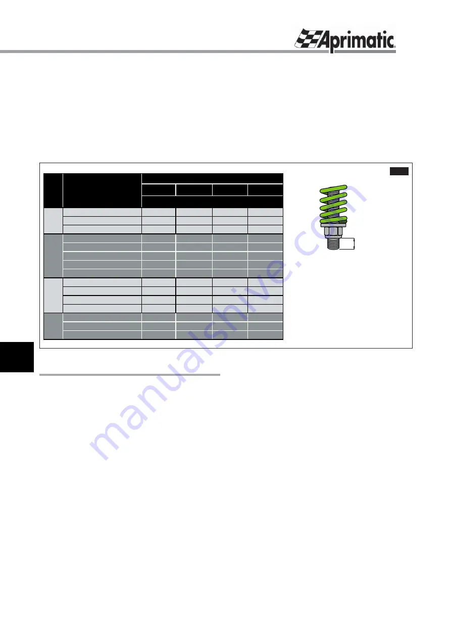
Als Anhaltspunkt für ein korrektes Ausbalancieren dient die 
Tabelle in 

Abb.10

. Sie zeigt die korrekten Schranke/Baum-

Kombinationen und jeweils dazu den am besten geeigneten 
Federtyp mit empfohlener Vorspannung (

Pos.H

).

Nach dem Ausbalancieren sollte man jedoch noch das 
Verhalten des Schrankenbaums bei den Öffnungs- und 
Schließvorgängen prüfen und eventuell eine Nachjustierung 
vornehmen.

8. INBETRIEBNAHME

1

. Mit dem Netzschalter die Stromzufuhr ausschalten.

2

. Die Seitentür mit dem mitgelieferten Schlüssel 

aufsperren.

3

. Die Schranke mit der Handkurbel ungefähr halb öffnen 

(siehe Abschnitt “

NOTBETÄTIGUNG

”).

4

. Die Kurbel von der Motorwelle ziehen;

5

. Die Tür wieder schließen.

Hinweis: Die Schrankentür unbedingt schließen, da 
sonst der Mikroschalter keinen Betrieb zulässt.

6

. Mit dem Netzschalter dei Stromzufuhr wieder einschalten 

und sicherstellen, dass an den Anschlussklemmen die 
richtige Spannung anliegt.

7

. Den Schalter der Steuerung auf Handbetrieb oder 

Halbautomatik (sofern vorgesehen) stellen.

8

. Einen Öffnungsimpuls geben und prüfen, ob sich die 

Schranke in die Öffnungsrichtung bewegt. Anderenfalls 
die Stromzufuhr unterbrechen, bevor der Baum die 
Endlage erreicht und die Anschlüsse am Motor oder an 
der Steuertafel  nach Bedarf vertauschen. Die Prüfung der 
Öffnungsrichtung wiederholen.

9

. Während der elektrisch gesteuerten Vorgänge prüfen, ob 

der Schrankenbaum an den gewünschten Endlagen anhält. 
Anderenfalls eine Einstellung vornehmen, um eventuell die 
durch Intensivnutzung entstehenden Spiele auszugleichen 

2,5 m

4 m

5 m

6 m

90x25

grün / 7

-

-

-

90x25 + Fuß

grün / 8

-

-

-

Ø 80

grün / 7

-

-

-

90x25

-

blau / 30

-

-

90x25 + Behang

blau / 36

-

-

-

90x25 + Fuß

-

blau / 36

-

-

90x25 + Fuß

blau / 38

-

-

-

Ø 80

-

blau / 20

-

-

90x25 + Behang

-

blau / 20

-

-

90x25 + Fuß

-

blau / 

22

-

-

Ø 80

-

blau / 14

rot / 25

-

rund teleskopisch

-

-

rot / 25

-

90x25 + Behang

-

rot / 25

-

-

Ø 80

-

-

gelb / 15

gelb / 17

rund teleskopisch

-

-

gelb / 15

gelb / 17

E50

X50

E60

X60

FEDER / H (mm)

Länge BAUM

E40-

X40

E25

X25

Baum und 

Zubehörteile

versione

HARRIER

Der Wert 

H

 zeigt die Position der 

Sicherungs- und Stellmutter der 
Feder, ausgedrückt in Millimeter freies 
Gewinde auf der Führungsstange an.

H

Abb.10

Содержание Harrier E25

Страница 1: ...en wobei die darin enthaltenen Anweisungen genau zu befolgen sind Nach dem Aufbau der Schranke muss erfahrenes Fachpersonal die korrekte Montage und den st rungsfreien Betrieb sicherstellen den Benutz...

Страница 2: ...one 5 4 4 Dimensioni d ingombro del corpo barriera 6 Installazione 5 1 Controlli e avvertenze preliminari 6 5 2 Ancoraggio della barriera al suolo 7 5 3 Cambio di mano della barriera 8 5 4 Montaggio m...

Страница 3: ...l installazione sia presente un interruttore magnetotermico differenziale adeguato Il produttore della motorizzazione declina ogni responsabilit qualora vengano utilizzati componenti non compatibili c...

Страница 4: ...da questo simbolo contengono informazioni su qualsiasi soggetto di particolare importanza il loro mancato rispetto pu comportare la perdita della garanzia contrattuale 4 CARATTERISTICHE DELLE BARRIERE...

Страница 5: ...5 Manovella asportabile per manovra manuale di emergenza fig 1 rif 6 Piastre per il fissaggio della centralina elettronica fig 1 rif 7 Carter di protezione con chiave di apertura fig 1 rif 8 Microinte...

Страница 6: ...sere adeguatamente ampia per l ingombro della sbarra in apertura e in chiusura vedi g 2 Il terreno dev essere solido e uniforme in particolare nelle zone d installazione dei componenti che appoggiano...

Страница 7: ...idotti in guaina essibile diametro minimo 30 mm per il passaggio dei cavi elettrici IMPORTANTE la super cie del plinto deve risultare perfettamente in bolla ed elevata sopra il livello del suolo di al...

Страница 8: ...rimento al par FINECORSA g 8 e alle istruzioni dell apparecchiatura di controllo per lo schema elettrico 5 4 MONTAGGIO MOLLA DI BILANCIAMENTO La barriera Harrier fornita priva di molla di bilanciament...

Страница 9: ...zza minima da terra di 1 5 m I collegamenti elettrici con gli accessori fotocellule lampeggiatore etc vanno effettuati come indicato in g 7 e tenendo in considerazione le speci che istruzioni fornite...

Страница 10: ...generale e accertarsi che ai morsetti di alimentazione giunga la corretta tensione 7 Portare il commutatore del quadro nella posizione manuale o semiautomatica se previsto 8 Dare un impulso di apertur...

Страница 11: ...ntare il precarico della stessa no a ottenere un movimento lineare sia in chiusura che in apertura Attenzione Prima di intervenire sul dado di regolazione della molla portare OBBLIGATORIAMENTE la sbar...

Страница 12: ...ella barriera stessa In caso di manovre manuali si raccomanda di prestare la massima attenzione e di RIMUOVERE SEMPRE LA MANOVELLA PRIMA DI RICHIUDERE IL PANNELLO LATERALE In caso di manutenzione RISC...

Страница 13: ...13 Italiano SPAZIO RISERVATO ALL INSTALLATORE SI PREGA DI CONSEGNARE QUESTA PAGINA ALL UTENTE Dichiarazione di conformit...

Страница 14: ...4 4 Barrier body external dimensions 18 Installation 5 1 Preliminary controls and precautions 18 5 2 Fixing the barrier to the ground 19 5 3 Changing the barrier con guration 20 5 4 Mounting the balan...

Страница 15: ...ensure that the available supply is compatible with the rating indicated on the data label Ensure that a correctly rated thermo magnetic differential breaker switch is tted upstream of the installati...

Страница 16: ...these indications may result in the guarantee being invalidated 4 HARRIER TECHNICAL SPECIFICATIONS 4 1 INTENDED USE AND APPLICATIONS The Harrier electro mechanical unit is designed to operate open and...

Страница 17: ...switch fig 1 ref 5 Removable crank for emergency manual operation fig 1 ref 6 Support plate for electronic control unit fig 1 ref 7 Protection panel with key fig 1 ref 8 Safety micro switch mounted o...

Страница 18: ...installation area must be large enough to fully accommodate the barrier in the open and closed positions see Fig 2 The installation area must be solid and at particularly in the areas where the compon...

Страница 19: ...th 2 exible cable conduits min diameter 30 mm for the electrical cables IMPORTANT The plinth surface must be perfectly level and raised above ground level by 20 mm Sink four tie bolts capable of secur...

Страница 20: ...g 8 and the control unit instructions for the electrical diagram 5 4 MOUNTING THE BALANCING SPRING Harrier is supplied without a balancing spring WARNING the spring should be mounted before the barri...

Страница 21: ...1 5 m above ground level Accessories photocells ashing lamps etc must be connected as indicated in g 7 and according to the speci c instructions provided with each device Fig 7 illustrates a complete...

Страница 22: ...correct 7 Set the selector switch on the electrical panel to manual or semi automatic if present 8 Command the barrier to open and check that it starts to move towards the open position if it moves i...

Страница 23: ...order to increase the loading strain until the barrier movement is linear when opening and closing Warning Before adjusting the spring nut the barrier MUST BE moved to the open position in order to d...

Страница 24: ...n case of manual operation always ensure that the CRANK IS REMOVED BEFORE REPLACING THE SIDE PANEL In case of maintenance COMPENSATION SPRING RELEASE HAZARD when the barrier is closed Quando l asta ab...

Страница 25: ...25 English SPAZIO RISERVATO ALL INSTALLATORE SI PREGA DI CONSEGNARE QUESTA PAGINA ALL UTENTE Dichiarazione di conformit...

Страница 26: ...ssaires l installation 29 4 4 Dimensions du corps de la barri re 30 Installation 5 1 Contr les et op rations pr liminaires 30 5 2 Ancrage de la barri re au sol 31 5 3 Changement de sens de la barri re...

Страница 27: ...l installation lectrique d un disjoncteur diff rentiel adapt Le fabricant de la motorisation d cline toute responsabilit en cas d utilisation de composants non compatibles avec une utilisation correc...

Страница 28: ...nformations sur tout sujet d importance particuli re le non respect de ces informations peut entra ner la perte de la garantie contractuelle 4 CARACTERISTIQUES DES BARRIERES HARRIER 4 1 USAGE PREVU ET...

Страница 29: ...canique fig 1 r f 5 Manivelle amovible pour manoeuvre manuelle d urgence fig 1 r f 6 Plaques pour fixation de la centrale lectronique fig 1 r f 7 Carter de protection avec cl d ouverture fig 1 r f 8 M...

Страница 30: ...uf samment grande pour contenir la barri re ouverte et ferm e voir g 2 S assurer que le sol est solide et uniforme notamment aux endroits o les composants prennent appui Estimer s il est n cessaire de...

Страница 31: ...2 conduits en gaine souple diam tre minimum 30 mm pour le passage des c bles lectriques IMPORTANT la surface du massif doit tre parfaitement de niveau et sur lev e d au moins 20 mm par rapport au niv...

Страница 32: ...du dispositif de contr le pour le sch ma lectrique 5 4 MONTAGE DU RESSORT D EQUILIBRAGE La barri re Harrier est fournie sans ressort d quilibrage ATTENTION le montage du ressort doit tre effectu avant...

Страница 33: ...1 5 m du sol Les branchements lectriques avec les accessoires cellules photo lectriques feu clignotant etc doivent tre effectu s comme indiqu en g 7 en tenant compte des instructions particuli res fou...

Страница 34: ...Mettre le commutateur du tableau en position manuelle ou semi automatique si pr vu 8 Donner une impulsion d ouverture et s assurer que la barri re s actionne dans le sens de l ouverture dans le cas c...

Страница 35: ...n d un mouvement lin aire aussi bien en ouverture qu en fermeture Attention Avant d agirsurl crouder glage du ressort amener IMPERATIVEMENT la barri re en position d ouverture pour d tendre le ressort...

Страница 36: ...ention maximale et de TOUJOURS RETIRER LA MANIVELLE AVANT DE REFERMER LE PANNEAU LATERAL Lors d op rations d entretien RISQUE DE DECROCHAGE DU RESSORT de compensation quand la barre est en position de...

Страница 37: ...37 Fran ais SPAZIO RISERVATO ALL INSTALLATORE SI PREGA DI CONSEGNARE QUESTA PAGINA ALL UTENTE Dichiarazione di conformit...

Страница 38: ...orderliche Bauteile zur Montage 41 4 4 Au enma e des Schrankenk rpers 42 Montage 5 1 Kontrollen und Vorbereitungen 42 5 2 Verankerung der Schranke am Boden 43 5 3 Seitenwechsel der Schranke 44 5 4 Mon...

Страница 39: ...r magnetthermischer Differentialschalter vorgeschaltet ist Der Antriebshersteller bernimmt keine Haftung bei Verwendung von Bauteilen die nicht mit einem korrekten und sicheren Gebrauch kompatibel sin...

Страница 40: ...dieses Symbol vorangestellt wird enthalten besonders wichtige Informationen Die Missachtung kann zum Verlust der vertraglichen Garantie f hren 4 EIGENSCHAFTEN DER HARRIER SCHRANKEN 4 1 BESTIMMUNGSZWE...

Страница 41: ...mechanischer Endschalter Abb 1 Pos 5 Abnehmbare Handkurbel zur Notbet tigung Abb 1 Pos 6 Befestigungsplatte f r elektronische Steuerung Abb 1 Pos 7 Schutzgeh use mit Schl ssel Abb 1 Pos 8 Mikrosicherh...

Страница 42: ...baums ffnen und Schlie en der Schranke sein siehe Abb 2 Der Boden muss fest und eben sein insbesondere an den Stellen an denen die auf dem Boden lagernden Bauteile installiert werden Abw gen ob eine S...

Страница 43: ...llen und 2 Leerrohre Mindestdurchmesser 30 mm zur Durchf hrung der Stromkabel einbringen WICHTIG Das Fundament muss eine vollkommen waagrechte Ober che haben und mindestens 20 cm aus dem Boden herausr...

Страница 44: ...Anschlussplan 5 4 MONTAGE DER AUSGLEICHSFEDER Die Schranke Harrier wird ohne Ausgleichsfeder geliefert ACHTUNG Die Montage der Feder muss vor Montage des Baums erfolgen Wenn ein Eingriff an der Feder...

Страница 45: ...ichtschranken Blinkleuchten usw m ssen entsprechend den Angaben in Abb 7 erfolgen wobei im Einzelnen die zu diesen Vorrichtungen gelieferten Hinweise zu beachten sind Abb 7 zeigt einen Anschlussplan m...

Страница 46: ...e Spannung anliegt 7 Den Schalter der Steuerung auf Handbetrieb oder Halbautomatik sofern vorgesehen stellen 8 Einen ffnungsimpuls geben und pr fen ob sich die Schranke in die ffnungsrichtung bewegt A...

Страница 47: ...sgleichsfeder Abb 12 die Vorspannung der Feder erh ht werden bis man eine lineare ffnungs und Schlie bewegung erzielt Achtung VorBet tigungderFederstellmutter MUSS die Schranke in die ffnungsposition...

Страница 48: ...Teilen der Schranke ausgeht Bei manuellen Bet tigungen mit u erster Vorsicht vorgehen und DIE KURBEL IMMER ENTFERNEN BEVOR DIE SEITLICHE T R WIEDER GESCHLOSSEN WIRD Bei Wartungen GEFAHR des herausspr...

Страница 49: ...49 Deutsch SPAZIO RISERVATO ALL INSTALLATORE SI PREGA DI CONSEGNARE QUESTA PAGINA ALL UTENTE Dichiarazione di conformit...

Страница 50: ...3 4 4 Dimensiones del cuerpo barrera 54 Instalaci n 5 1 Controles y advertencias preliminares 54 5 2 Anclaje de la barrera al suelo 55 5 3 Cambio de mano de la barrera 56 5 4 Montaje del muelle de equ...

Страница 51: ...r magnetot rmico diferencial adecuado El productor de la motorizaci n declina cualquier responsabilidad si se utilizan componentes incompatibles con un uso correcto y seguro El instalador debe suminis...

Страница 52: ...Informaciones Las indicaciones precedidas por este s mbolo contienen informaciones de cualquier tipo que si no se respetan conllevan la p rdida de validez de la garant a 4 CARACTER STICAS DE LAS BARRE...

Страница 53: ...5 Manivela desmontable para maniobra manual de emergencia fig 1 ref 6 Placas de sujeci n de la central electr nica fig 1 ref 7 C rter de protecci n con llave de apertura fig 1 ref 8 Microinterruptor...

Страница 54: ...amplia para la barrera en apertura y en cierre v ase g 2 El terreno debe ser s lido y uniforme en concreto las zonas de instalaci n de los componentes que se apoyan en el suelo Evaluar la necesidad de...

Страница 55: ...cables el ctricos IMPORTANTE la super cie de la base debe resultar perfectamente nivelado y hallarse por encima del nivel del suelo unos 20 mm como m nimo Hay que colocar los ganchos de cimentaci n p...

Страница 56: ...ctrico 5 4 MONTAJE MUELLE DE EQUILIBRADO La barrera Harrier se suministra sin muelle de equilibrado ATENCI N el montaje del muelle se efect a antes de montar la barra Si se debe intervenir en el muell...

Страница 57: ...icas intermitentes etc se efect an seg n lo indicado en la g 7 y teniendo en cuenta las instrucciones espec cas de acompa amiento de cada uno de ellos La g 7 ilustra una instalaci n t pica con los com...

Страница 58: ...s bornes 7 Llevar el conmutador del cuadro a la posici n manual o semiautom tica si la hubiera 8 Dar el impulso de apertura y asegurarse de que la barra se mueva en el sentido de apertura si esto no s...

Страница 59: ...mentar la precarga del muelle y hasta obtener un movimiento lineal tanto en cierre como en apertura Atenci n Antes de intervenir en la tuerca de regulaci n del muelle ES OBLIGATORIO llevar la barra en...

Страница 60: ...arrera En el caso de maniobras manuales se aconseja prestar la m xima atenci n y SIEMPRE SACAR LA MANIVELA ANTES DE CERRAR EL PANEL LATERAL En el caso de mantenimiento RIESGO DE DESENGANCHE DEL MUELLE...

Страница 61: ...61 Espa ol SPAZIO RISERVATO ALL INSTALLATORE SI PREGA DI CONSEGNARE QUESTA PAGINA ALL UTENTE Dichiarazione di conformit...

Страница 62: ...Aprimatic S p A via Leonardo da Vinci 414 40060 Villa Fontana di Medicina Bologna Italy tel 39 051 6960711 fax 39 051 6960722 info aprimatic com www aprimatic com...

Страница 63: ...C gnd ARMOIRE G1 PRO R cepteur U ICO SE PC12 E ER4 SCHEMA DE RACCORDEME T BARRIERE HARRIER SERIE E X AVEC ARMOIRE G1 PRO ET20 Commun bleu gris Ouverture Fermeture Condensateur Fin course ouverture Fin...

Страница 64: ...S curit auxiliaire N C 24 Voyant clignotant Commande clignotant Commande voyant 24V 3 watts max 1 2 3 4 ARMOIRE TRAFFIC 230 Fin course ouverture noir Fin course fermeture marron Commun bleu gris C NC...

Отзывы: