-
20
-
English
6
10
1
2
9
7
6
8
5
3
3
4-5
5.3
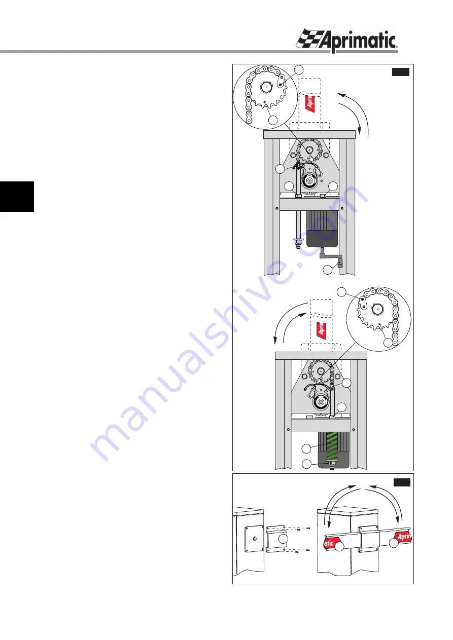
CHANGING THE BARRIER CONFIGURATION
The barrier is supplied in the right hand confi guration,
to change it to the left hand confi guration, proceed as
follows.
n.b.:
If it is necessary to change the confi guration, it is best to
do so before mounting the barrier and the spring.
1
. Remove the link (
fi g.5-ref.1
) between the chain and
the spring tensioning rod and slide the rod out through the
ferrule (
fi g.5-ref.2
).
WARNING
: If this operation is to be carried
out with the spring already mounted, it should be discharged
by loosening the corresponding locking and adjustment nut
(
fi g.5-ref.8
- if the barrier is mounted it must be moved to the
vertical position).
2
. Remove the link (
fi g.5-ref.3
) between the chain and the
gear.
3
. Wind the chain around the gear in the opposite direction
so that it covers an arc of 180° and insert the link pin (
fi g.5-
ref.4
) in the other available hole (
fi g.5-rif.5
).
4
. Insert the tensioning rod through the ferrule (
fi g.5-ref.6
)
and reconnect it to the chain using the link from point 1
(
fi g.5-ref.7
).
IMPORTANT
: in case of a left hand barrier, the motor and
limit switch connections must be inverted
(
see para. “LIMIT
SWITCHES” fi g.8
and the control unit instructions for the
electrical diagram)
.
5.4
MOUNTING THE BALANCING SPRING
Harrier
is supplied without a balancing spring.
WARNING:
the spring should be mounted before the
barrier - if it is necessary to work on the spring when the
barrier has already been mounted, it should be raised to
the vertical position using the emergency operating crank
supplied (
fi g.5-ref.10
).
Select the appropriate spring for the installation and mount
it as follows:
1
. Unscrew the spring locking and adjustment nut (
fi g.5-
ref.8
).
2
. Insert the appropriate spring along the tensioning rod/
guide (
fi g.5-ref.9
).
3
. Re-tighten the spring locking and adjustment nut (
fi g.5-
ref.8
).
n.b.:
once the installation and electrical connection procedures
have been completed, the barrier must be balanced and
checked (see
para. “BALANCING THE BARRIER”
).
5.5 MOUNTING
THE
BARRIER
1
. Position the barrier mounting fl ange as shown in
fi g.6-
ref.1
.
2
. Secure the fl ange using the 4 screws provided, without
fully tightening them.
3
. Insert the barrier in the fl ange in the horizontal position
shown in
fi g.6-ref.A
for the right hand confi guration (this
means that when it is viewed from the barrier side, it opens
clockwise), or as shown in
fi g.6-ref.B
for the left hand
confi guration.
4
. After checking the length, tighten the screws securing
the fl ange.
Installation
A
B
1
fig.6
fig.5
RIGHT HAND
BARRIER
LEFT HAND
BARRIER


