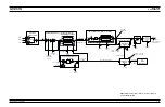


formance. The frequency ranges of the three paths
are 20 to 25 GHz, 25 to 32 GHz, and 32 to 40 GHz.
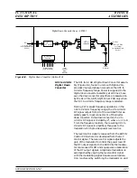
After routing through the appropriate bandpass fil-
ter path, the 20 to 40 GHz RF signal is multiplexed
by the PIN switches to the SDM output at connector
J2. RF signals input to the SDM of
£
20 GHz are
multiplexed through by the PIN switches to output
connector J2.
From J2, the RF signal goes to either the directional
coupler (
£
40 GHz models) or the input connector J2
of the forward coupler (>40 GHz models).
In units with Option 22, the RF signal from J2 goes
to input connector A of the diplexer where it is di-
plexed with the 0.00001 to 2 GHz RF signal (from
the down converter and A13 10 MHz DDS PCB) into
the RF path to either the directional coupler
(
£
40 GHz models) or the input connector J2 of the
forward coupler (>40 GHz models).
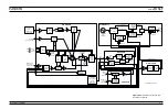
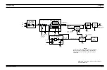
Source
Quadrupler
Module
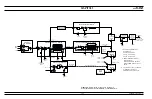
The source quadrupler module (SQM), found in
>40 GHz models, is used to quadruple the funda-
mental frequencies of 10 to 16.25 GHz to produce
RF output frequencies of 40 to 65 GHz. The RF sig-
nal inputs for the SQM come from the switched fil-
ter assembly. The modulator control signal for the
SQM is received from the A14 YIG, SDM, SQM
Driver PCB where it is developed from the ALC con-
trol signal. The A14 PCB also supplies the amplifier
bias voltage(s) for the SQM.
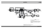
Model 69077B/69177B (SQM P/N D28185)
During CW and swept frequency operations in the
40 to 50 GHz frequency range, the 10 to 12.5 GHz
RF signal input is quadrupled and amplified, then
goes to the modulator. The modulator provides for
power level control and, in the 69177B, amplitude
modulation of the RF output signals. From the
modulator, the 40 to 50 GHz RF signals goes via a
band-pass filter to output connector J3 of the for-
ward coupler. Note that on the 40 to 50 GHz SQM
(P/N D28185), the forward coupler is an integral
part of the SQM. The 0.01 to 40 GHz RF output sig-
nals from the SDM (0.00001 to 40 GHz RF output
signals from the diplexer for 69077B/69177Bs with
Option 22) are routed to input connector J2 of the
SQM forward coupler. The 0.01 to 50 GHz (0.00001
to 50 GHz for 69077B/69177Bs with Option 22) RF
output signals go from J3 of the SQM forward cou-
pler to the directional coupler.
690XXB/691XXB MM
2-29
FUNCTIONAL
RF DECK
DESCRIPTION
ASSEMBLIES
Содержание 680 C Series
Страница 4: ......
Страница 5: ......
Страница 13: ...Figure 1 1 Typical Series 690XXB 691XXB Synthesized CW Signal Generator Model 69187B Shown ...
Страница 61: ......
Страница 97: ......
Страница 205: ......
Страница 207: ......
Страница 221: ......
Страница 225: ......
Страница 241: ......
Страница 259: ......
Страница 275: ......
Страница 285: ......
Страница 289: ......
Страница 299: ......
Страница 303: ......
Страница 315: ......


