


NOTE
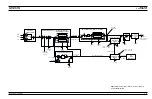
The instrument uses two internal level de-
tection circuits. For frequencies <2 GHz
(
£
2.2 GHz for units with Option 21A), the
level detector is part of the Down Con-
verter. The signal from this detector is
routed to the A10 ALC PCB as the Detector
0 input. For frequencies
³
2 GHz (>2.2 GHz
for units with Option 21A), the level detec-
tor is part of the main Directional Coupler.
The signal from this detector is routed to
the A10 ALC PCB as the Detector 1 input.
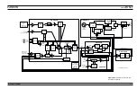
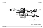
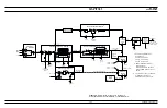
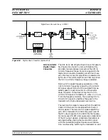
The Level Reference DAC, under the control of the
CPU, provides the RF level reference voltage. By
setting the output of this DAC to the appropriate
voltage, the CPU adjusts the RF output power to the
level selected by the user. Leveled output power can
be set over a maximum range of up to 33 dB (up to
149 dB with the Option 2 step attenuator) using
front panel controls or the GPIB. Instruments with
Option 15A (High Power) provide leveled output
power over a maximum range of up to 27 dB (up to
141 dB with the Option 2 step attenuator).
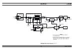
External Leveling
In the external leveling mode, an external detector
or power meter monitors the RF output level of the
690XXB/691XXB instead of an internal level detec-
tor. The signal from the external detector or power
meter goes to the A10 ALC PCB from the front or
rear panel inputs. The ALC controls the RF power
output level as previously described.
ALC Slope
During analog sweeps (691XXB only), a slope-vs-
frequency signal, from the A12 Analog Instruction
PCB, is summed with the level reference and detec-
tor inputs into the ALC loop. The Slope DAC, under
the control of the CPU, adjusts this ALC slope sig-
nal to compensate for an increasing or decreasing
output power-vs-frequency characteristic caused by
the level detectors and (optional) step attenuator. In
addition (in both the 690XXB and the 691XXB), the
Slope DAC lets the user adjust for the slope-vs-
frequency characteristics of external components.
2-16
690XXB/691XXB MM
FUNCTIONAL
ALC AND
DESCRIPTION
MODULATION
Содержание 680 C Series
Страница 4: ......
Страница 5: ......
Страница 13: ...Figure 1 1 Typical Series 690XXB 691XXB Synthesized CW Signal Generator Model 69187B Shown ...
Страница 61: ......
Страница 97: ......
Страница 205: ......
Страница 207: ......
Страница 221: ......
Страница 225: ......
Страница 241: ......
Страница 259: ......
Страница 275: ......
Страница 285: ......
Страница 289: ......
Страница 299: ......
Страница 303: ......
Страница 315: ......


