


690XXB/691XXB MM
5-37
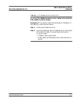
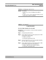
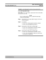
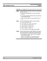
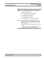
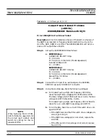
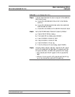
Step 5.
Connect the X input of an oscilloscope to the 690XXB/
691XXB rear panel
HORIZ OUT
connector.
Step 6.
Using the oscilloscope, check for a –0.2 to –3.5 volt YIG tun-
ing ramp at A14TP10.
q
If the ramp signal is correct, go to step 7.
q
If the ramp signal is incorrect or not present, replace the
A14 PCB.
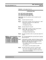
Step 7.
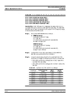
Using the oscilloscope, check for the YIG bias voltages at the
test points shown in Table 5-19A.
q
If the YIG bias voltages are correct, replace the YIG-
tuned oscillator assembly.
q
If the YIG bias voltages are incorrect, replace the A14
PCB.
Step 8.
Run self-test again.
q
If no error message is displayed, the problem is cleared.
q
If any of the error messages, listed above, are displayed,
contact your local Anritsu service center for assistance.
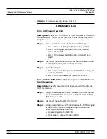
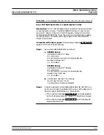
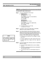
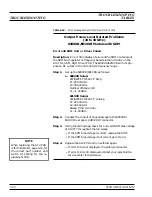
Table 2-18.
Error Messages 124, 125, and 126 (4 of 4)
TROUBLESHOOTING
TROUBLESHOOTING
TABLES
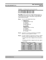
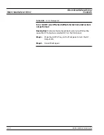
Test Point
YIG-tuned Oscillator Bias Voltages
2 to 8.4 GHz
8.4 to 20 GHz
A14TP5
+7V
+7V
A14TP3
0V
+8V
A14TP4
–5V
–5V
A14TP2
+8V
0V
Table 5-19A.
YIG-tuned Oscillator Bias Voltages
NOTE
When replacing the A14 PCB,
refer to Table 6-1, page 6-12, for
the correct part number and
switch S1 setting for the re-
placement PCB.
Содержание 680 C Series
Страница 4: ......
Страница 5: ......
Страница 13: ...Figure 1 1 Typical Series 690XXB 691XXB Synthesized CW Signal Generator Model 69187B Shown ...
Страница 61: ......
Страница 97: ......
Страница 205: ......
Страница 207: ......
Страница 221: ......
Страница 225: ......
Страница 241: ......
Страница 259: ......
Страница 275: ......
Страница 285: ......
Страница 289: ......
Страница 299: ......
Страница 303: ......
Страница 315: ......


