


4-13
FM CALIBRATION
(691XXB ONLY)
This procedure provides the steps necessary to perform FM calibra-
tion. This consists of calibrating the FM Meter circuit and the FM
Gain Control DAC. The FM Gain Control DAC is calibrated for input
sensitivities in both narrow and wide FM modes.
Equipment
Setup
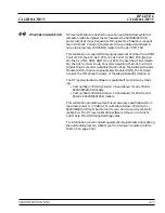
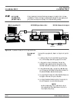
Connect the equipment, shown in Figure 4-9, as fol-
lows:
1. Interface the PC to the 691XXB by performing
the initial setup procedure, pages 4-7 to 4-12.
2. Connect the 691XXB rear panel
10 MHz REF OUT
to the Spectrum Analyzer External Reference in-
put.
3. Connect the Function Generator Output to the
BNC tee. Connect one leg of the tee to the
691XXB front panel
FM IN
. Connect the other leg
of the tee to the DMM input.
4. Connect the 691XXB
RF OUTPUT
to the Spec-
trum Analyzer RF Input.
4-34
690XXB/691XXB MM
S e r i a l
I / O
6 9 1 X X B S i g n a l G e n e r a t o r
C O M 1
o r
C O M 2
I B M - C o m p a t i b l e P C
F u n c t i o n
G e n e r a t o r
1 0 M H z
R E F O U T
E X T R E F
I N P U T
R F
I N
S p e c t r u m
A n a l y z e r
O U T P U T
F M
I N
R F
O U T P U T
B N C
T e e
I N P U T
D M M
Figure 4-9.
Equipment Setup for FM Calibration
FM
CALIBRATION
CALIBRATION
Содержание 680 C Series
Страница 4: ......
Страница 5: ......
Страница 13: ...Figure 1 1 Typical Series 690XXB 691XXB Synthesized CW Signal Generator Model 69187B Shown ...
Страница 61: ......
Страница 97: ......
Страница 205: ......
Страница 207: ......
Страница 221: ......
Страница 225: ......
Страница 241: ......
Страница 259: ......
Страница 275: ......
Страница 285: ......
Страница 289: ......
Страница 299: ......
Страница 303: ......
Страница 315: ......


