background image

13

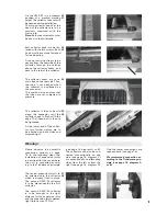
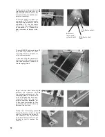
The sensor is to be pushed into 

the collector up to the stop, i.e. 

approximately 19 cm. This is the 

correct position for precise tem-

perature recording.

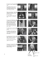
The blind cover is placed on 

connection “B”. The cold water 

supply to the collector is fed to 

connection “A”; the hot water 

return from the collector exits 

at connection “C”. (Sensor has 

been removed to improve clar-

ity.)

The two OWR 20 collectors have 

now been mounted on their 

mounting frames and hydrauli-

cally interconnected. 

In the next step, the entire col-

lector array is to be fastened to 

the base surface by means of 

the clamping plates.

27

25

26

30

31

28

29

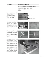
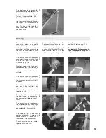
Begin with the base fastening 

between the collectors. With 

the supports extension set, the 

clamping plate is to be slid in 

until it reaches the slot nuts. 

Important: Push the two alu-

minium sections together un-

til the plate is clamped in. This 

guarantees the correct distance 

between the sections.

Finally, the 4 clamping plates 

(two at the front, and two at the 

rear) for fastening the edges of 

the collector array are bolted 

tight. Each plate must also be 

pushed in until it reaches the 

slot nut. 


C

 Collector outlet / 

hot

B

 Collector inlet / 

cold

A

 Internal  

return pipe / 

collector inlet

Содержание OWR 20

Страница 1: ...nstallation Commissioning 05 14 Manufactured in Switzerland by www amk collectra ch Distributed by www amk solac com Should you have any technical questions please contact your sales consultant of your supplier OWR 20 optimized without reflector ...

Страница 2: ...ot be confused Expansion vessel The correct connection of the expansion vessel is determined by the site management The pre charge pressure must be adjusted before the filling of the system Expansion vessel pre charge pressure Ok collector up to middle of expansion vessel in bar 0 5 bar but at least at 1 0 bar Pressure test After the mounting of the collector field solar pipes pump groups and the ...

Страница 3: ...systems 14 OWR 20 dimensioning 15 IIb Hydraulic connections 16 IIc Expansion vessel Expansion vessel calculation 17 Intrinsically safe solar system 18 Example expansion vessel calculation 20 IId Protective devices Lightning protection 22 Scald protection 22 Overheating protection 22 Safety valve 22 IIe Maintenance Repair 23 Tyfocor LS is a complete mixture Don t mix with water ...

Страница 4: ...ng installation care must be taken to keep all outdoor pipes as short as pos sible Sensor installation For trouble free functioning of the entire system the sensor must be inserted 19 cm into the provided sensor well in the col lector on the input output side Devices Fittings For trouble free functioning of the entire system it is impera tive to install the devices and fittings described in the pr...

Страница 5: ... 1 pc angular frame OWR 20 the following number of attachments BS A per BS L is required These numbers are valid for collector fields with 2 collectors and more 3 angular frames and more The volume flow per module is 1 7 l min or 102 l h The fluid is a ready to use evapo ration proof special heat exchange liquid on 1 2 propylene glycol ba sis Tyfocor LS is not harmful to health and the corrosion i...

Страница 6: ...es and the connector will later come to be located on the same side The connectors once screwed together are now ready to be fastened to the roof Note It is advantageous to avoid connecting more than two connectors This simplifies handling on the roof Choose the installation location rafters spacing and distance from the tiles for the mounting angles and the position of the connectors Flexible dis...

Страница 7: ... recess Put the mounting angle in place position the drill holes with the wood screws and pre drill the holes with a drill bit of approxi mately 5 5mm diameter The wood screws can be quickly tightened with the socket span ner Mounting angle screwed firmly in place with additional wooden support for correct tile height The mounting angles can also be installed with a lateral offset The flexible mou...

Страница 8: ... It is advantageous for the groove to be at the bottom as shown here This reduces the torque required for fastening the collector Both connectors for two OWR 20 collectors are pre assembled This means that the connectors span unfavourable distances between rafters and allow dif ferent distances from the edge Flexible connector support 15 16 17 18 19 Eternit roof The same instruction steps as shown...

Страница 9: ...dge The T head bolt is then to be tightened At the lower end of the collec tor two further clamps are to be attached on both sides and screwed tight The central expansion joint is to be screwed onto the collector which is already fixed in place The second OWR 20 collector is to be placed nearby the first collector The second OWR 20 collector is to be brought to the right distance for the expansion...

Страница 10: ...collector s input and output side This requires piercing the rubber plug for example with a 5mm drill bit The rubber plug is to be com pletely pulled out in order to make sure that the sensor is inserted into the sensor well The sensor is then to be inserted together with the plug The sensor is to be pushed into the collector up to the stop i e approximately 19 cm This is the correct position for ...

Страница 11: ... basic set and one extension set are to be laid out as shown here Note The mounting frames are not to be bolted tight to the clamps at the base until the end of the mounting procedure The polystyrene and the battens are to be arranged as shown opposite the mounting frame sections The OWR 12 collector is to be laid onto the battens and poly styrene with the rear side facing upwards Note The tubes m...

Страница 12: ... by itself Remove the slot nut with a trian gle from the standing section Slide in the slot nut with a trian gle at the head of the collector Note This fastening measure ment must later be repeated for all collectors exact to the mil limetre After measuring tighten the two bolts Once both triangles have been fastened at the head of the col lector the collector is to be tilted over the pivotal poin...

Страница 13: ... squeeze the expansion joints together a little Screw the U bend in place With the blind cover all connections are now sealed torque max 15 Nm The sensor is to be inserted on the collector s input and output side Pierce the rubber plug for example with a 5mm drill bit The rubber plug is to be com pletely pulled out in order to make sure that the sensor is inserted into the sensor well The sensor i...

Страница 14: ...e entire col lector array is to be fastened to the base surface by means of the clamping plates 27 25 26 30 31 28 29 Begin with the base fastening between the collectors With the supports extension set the clamping plate is to be slid in until it reaches the slot nuts Important Push the two alu minium sections together un til the plate is clamped in This guarantees the correct distance between the...

Страница 15: ...nergy Western pump is idle At midday Both pumps are running Energy is being sup plied from eastern and western collector array sections In the afternoon Western pump is running because the western collector array section is produc ing energy Eastern pump is idle N B Only one expansion ves sel is to be connected to the 3 strand pump group Legend S1 Eastern collector sensor S2 Western collector sens...

Страница 16: ...300 ltr 2 3 Pers 300 ltr 1 Pers 200 ltr 1 5 5 1 7 0 6 CU SR 18x1 0 15x 18x1 0 15x 18x1 0 15x 3 5 Pers 400 ltr 5 Pers 400 ltr 5 Pers 400 ltr 2 4 Pers 300 ltr 2 10 9 3 4 1 3 CU SR 18x1 0 15x 18x1 0 15x 18x1 0 15x 3 6 Pers 500 ltr 6 Pers 500 ltr 6 Pers 500 ltr 6 Pers 400 500 ltr 3 16 4 5 1 4 2 CU SR 18x1 0 20x 18x1 0 20x 18x1 0 20x 4 6 8 Pers 750 ltr 6 8 Pers 750 ltr 6 8 Pers 750 ltr 6 Pers 500 ltr 4...

Страница 17: ...e first and last collectors as shown Corresponding one sided con nection on the right hand side Large scalesystems Tichelmann Large scale systems e g more than 6 OWR 20 collectors in a row can be connected together in the centre of the array for quick low loss yields II Commissioning IIb Hydraulic connections Do not fill the system in direct sunlight Danger of steam hammering Sensor Attention We r...

Страница 18: ...nt V S i e the sum of the content of any stor age tanks pipes radiators etc in the solar system Maximum supply tempera ture tsupply for the heating system s dimensioning condi tions System s static height Hp i e height from the centre of the tank to the system s highest bleed point cf fig For systems with a maximum supply temperature above boil ing point at atmospheric pres sure the saturation pre...

Страница 19: ... suitable cooling line e g coiled pipe or cooling vessel in front of the expansion vessel Automatic bleed valves We do not recommend automatic bleed valves If however there is no alternative automatic bleed valves must always be installed verti cally It is only permissible to install automatic bleed valves or similar systems if a tight sealing manual shut off valve e g ball valve is situated immed...

Страница 20: ...2 5 11 0 10 0 8 5 7 5 6 0 5 0 3 8 2 5 1 3 SD 80 40 0 37 6 36 0 33 6 32 0 29 6 28 0 25 6 24 0 21 6 20 0 17 6 16 0 13 6 12 0 9 6 8 0 6 0 4 0 2 0 SU standing tanks SU 140 70 0 65 8 63 0 58 8 56 0 51 8 49 0 44 8 42 0 37 8 35 0 30 8 28 0 23 8 21 0 16 8 14 0 10 5 7 0 3 5 SU 200 100 0 94 0 90 0 84 0 80 0 74 0 70 0 64 0 60 0 54 0 50 0 44 0 40 0 34 0 30 0 24 0 20 0 15 0 10 0 5 0 SU 300 150 0 141 0 135 0 12...

Страница 21: ...ncrease The thermal expan sion factor F indicated for 110 C in the table on p 17 is approx 0 051 i e 5 1 To a large extent the collectors water content will transform into vapour see p 18 Intrinsically safe solar system 2 Calculation of pre charge pressure and determination of expansion vessel Correct calculation and setting of the pre charge pressure at the ex pansion vessel air side guarantees t...

Страница 22: ... at filling station C at connection A0 Bleed valve 3 on the solar station SSt is closed see arrow The heat transfer medium flows via A1 back into filling station E The heat transfer medium is pumped through the solar circuit until no more air bubbles appear in the flow of heat transfer medium at output E NOTE The pump on the solar station SSt must be turned on when the filling pressure in the syst...

Страница 23: ...er minals can be realised at the collector frame On both the sup ply and return sides the solar circuit piping is to be connected to the building s equipotential bonding via a short route Connect the connector to the collector s lightning protection connections For system sizes 200m2 gross surface area connect a light ning conductor on the left and the right For system sizes 200m2 gross surface ar...

Страница 24: ...e re placed 5 When reinstalling first insert the expansion joints Only then are the fastening bolts to be tightened on the collector hooks See installation instructions described earlier Tube replacement without collector removal 1 Squeeze together the cover s base clips and remove Remove any glass or glass residues Sweep glass dust out of the col lector with a fine fibre brush 2 Insert new tube a...

Отзывы: