8
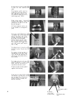
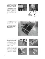
Lie the OWR 20 in a horizontal
position at a practical working
height. The collector hook set will
be needed during installation.
The two collector hooks at the
head of the collector are to be
precisely measured with the
metre rule.
Note:
Both measurements must
be exact to the millimetre.
Each collector hook is to be fas-
tened with the two screws. Each
hook must be securely fastened
for load bearing.
A rope or carrying strap is to be
passed from the rear side of the
collector, through the notches
above the collector hooks, and
back to the rear of the collector.
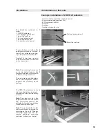
The collector hooks are to re-
main free on the rear side. Thus,
the rope is not pinched when
the collector is positioned on
the connector.
This method also ensures that
the tubes are not subjected to
pressure.
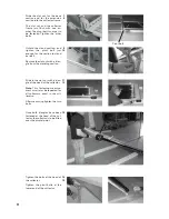
The collector is then to be slid
along the connector until the
collector hook is flush with the
edge. The T-head bolt is then to
be tightened.
At the lower end of the collec-
tor, two further clamps are to
be attached on both sides and
screwed tight.
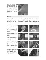
The central expansion joint is to
be screwed onto the collector
which is already fixed in place.
The second OWR 20 collector
is to be placed nearby the first
collector.
The second OWR 20 collector
is to be brought to the right
distance for the expansion joint
and the expansion joint screwed
tight (torque max. 15 Nm).
20
21
22
23
24
25
26
27
28
Warning!
Please observe the hydraulic
connection variants on page
16. In the following steps, the
installation of expansion joints
is described for the case where
the unit is connected accord-
ing to the Tichelmann principle
(see page 16, diagram A or B).
The collectors can also be con-
nected conventionally on one
side (see page 16, diagram C)
or conventionally on alternating
sides from the left or from the
right (see page 16, diagram D).
Only the lower connections are
required here (see page 16).
We recommend connection ac-
cording to the Tichelmann prin-
ciple (see page 16, diagram A
or B).


