22
Lightning protection
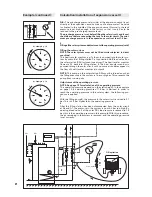
In the storage tank or the wa-
ter heater, very high domestic
hot water temperatures can
sometimes arise. For protec-
tion against scalding at the stor-
age tank output, a thermostatic
3-way mixing valve is to be in-
stalled and configured so that
Scald protection
Under certain operating condi-
tions, solar systems may over-
heat during operation. This is re-
sponded to by the safety valve.
For example:
– No demand for energy from
the solar storage tank, e.g. the
users are on summer holiday.
– The solar system was dimen-
sioned to also provide space
Overheating protection (if not an intrinsically safe system)
the temperature at the tap is
limited to around 50°C.
This mixer (TMV) should be
installed in close proximity to
the storage tank. It must be en-
sured that there is equal water
pressure at both of the mixer's
inputs.
heating in the winter months,
thus there is an energy surplus
in summer.
The surplus energy can be dis-
posed of as follows:
– Heat dissipation during the
night via the solar collectors,
i.e. in the night, the solar circuit
pump activates and cools the
storage tank via the collector.
– The surplus energy is trans-
ferred to a radiator or swim-
ming pool.
Overheating protection is guar-
anteed by setting the desired
temperatures at the solar con-
troller: see solar controller in-
struction manual.
As a general rule, all electrical
devices must be earthed with
a metal housing. This also ap-
plies to solar systems. Pump
group, pipes, storage tank and
collectors must be equipped
with equipotential bonding, i.e.
they must be connected to earth
just like normal water pipes. The
earthing requires a highly con-
ductive connection between the
earthing point and the collector.
The installation of earthing ter-
minals can be realised at the
collector frame. On both the sup-
ply and return sides, the solar
circuit piping is to be connected
to the building's equipotential
bonding via a short route.
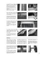
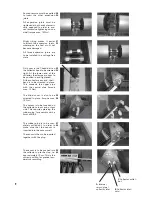
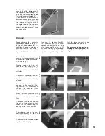
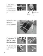
Connect the connector to the
collector's lightning protection
connections.
For system sizes < 200m2 (gross
surface area), connect a light-
ning conductor on the left and
the right. For system sizes >
200m2 (gross surface area), add
an additional connection to a
lightning conductor for every
200m2.
Note:
It is imperative to observe
the local regulations.
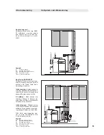
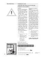
Safety valve
For OWR collectors, safety
valves with 6.0 bar activation
pressure should be installed.
Dimensioning
Dimensioning of safety valves
occurs in accordance with the
general guidelines for 6 bar de-
activation pressure:
- Safety valve
1/2”
max. 75kW
- Safety valve
3/4”
max. 150kW
- Safety valve
1”
max. 445kW
Positioning
Ahead of the shut-off valves in
the solar supply or return.
The pressure capacity of the
expansion vessel must suit the
activation pressure of the safety
valve (SV), e.g. SV activation
pressure 6.0 bar = min. expan-
sion vessel pressure capacity 6.0
bar; smaller expansion vessels
have higher pressure capacity.
Closed systems must be
equipped with an additional
safety valve in the solar circuit.
It must be ensured that the con-
nection between the solar col-
lectors and the safety valve can-
not be shut off. In order to pre-
vent the heat transfer medium
from boiling too often, a safety
valve with shut-off pressure of
6 bar is to be provided for, i.e.
all system components must be
designed and approved for this
pressure.
Lay the connections leading to
the safety valve in such a way
that no dirt or the like can accu-
mulate within them. Ensure that
there are no prohibited constric-
tions, and no pipe bends small-
er than 3d.
II Commissioning
IId Protective devices
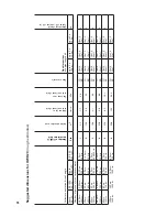
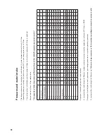
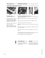
Wind load calculations are to be carried out as per local regulations (see also table on page 4).
Wind load calculations

