background image


Page 22 

Setting Volume Zones 

The Rock-Star Lx Digital Downloading Jukeboxes 
have the capability of controlling up to four 
independent volume zones when using Rowe’s IR 
Remote, Rock-Ola’s Multi-Zone Volume Control, or 
Rowe’s Digital Volume Control Unit (VCU). An 
optional power amplifier may be required for some 
situations. 
 

Volume Control (Zone) Linking 

There may be times when you do not want a location 
to have separate control of the internal and external 
amplifiers. Or perhaps you want two or more areas to 
have separate volume control. SyberSonic’s 
advanced electronic system allows “linking” of its 
volume controls. 
When linked, pressing either the Internal or External 
(1 and 2 on remote) buttons will cause the linked 
channels volume to change. 
 

Indicator LEDs 

The Digital SyberSonic Pre-Amplifier has LEDs to 
give a visual indication of its operating condition and 
status. The LEDs and their functions are as follows: 


Power -

 When lit it indicates the amplifier has power. 

Status - 

Indicates when the paging system 

(microphone) is active. 

Steady On – 

Normal operation. Paging system is 

available. 

Flashing – 

Paging system is in use. 

COM


– 

Indicates when the pre-amplifier receives 

instructions from the jukebox’s Core Computer. 

Always Off – 

Indicates a communication fault 

between the pre-amplifier and Core Computer. 

Single One Second Flash on Power Up – 

Pre-

Amplifier Processor is running. 

Steady Heartbeat – 

Normal operation 

communicating with the Core. Setup instructions 
received and installed. 

Steady On – 

Communication fault. Pre-Amplifier 

initially received computer commands, but then 
lost communication. 

Flickering or Intermittent Flashing – 

Pre-

Amplifier is receiving instructions from Jukebox 
Core Unit. 

Mute – 

When lit it indicates the control amp outputs 

are muted. 

Signal Inputs and Outputs 

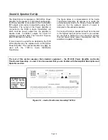
The Digital SyberSonic Pre-Amplifier has five (5) sets 
of RCA type jacks.


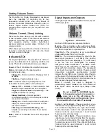
Figure 4-C – RCA Jacks 

Each set of RCA jacks has separate functions: 

Main In


– 

This connection is the audio signal that is 

being fed directly from the Sound Card in the Core 
Unit Audio Output into the pre-amplifier. 

Fixed Out


– 

This connection is an unconditioned 

analog audio output from the Core unit.


BGM In


– 

This connection allows the input of a line 

level signal (maximum 1 volt RMS) from another 
audio source (such as a tape player, TV, or FM tuner) 
to be fed into the pre-amplifier for auxiliary 
background music amplification.  The BGM volume 
level may be set separately, or linked to change 
along with the normal play volume. The background 
music inputs have level trim controls. These are small 
screw-driver adjustable potentiometers located 
between the two RCA jacks. Carefully adjust them to 
set the level of the background music as desired. The 
AVC will act on this signal to try and maintain it even 
if the location changes the level externally. 

Note:

 If enabled, this input is designed to 

automatically switch between the AUX BGM and 
Main inputs, where the Main input always takes 
priority. 

WARNING 

Do not connect the AUX BGM Inputs 
to the speaker outputs of a receiver or 
power amp, as this will damage the 

jukebox amplifier and void its warranty. Use a 
line converter with an actuator if necessary. 


Int. Out


Left & Right – 

These connections are a 

variable-level output signal directly from the pre-amp. 
In the default configuration, the signal level follows 
the internal volume control. If the optional Multi-Zone 
Volume Control is used, channels 1 and 2 control 
these signal levels respectively. 

Ext. Out

 - 

Left & Right – 

These connections are a 

variable-level output signal directly from the pre-amp. 
In the default configuration, the signal level follows 
the external volume control. If the optional Multi-Zone 
Volume Control is used, channels 3 and 4 control 
these signal levels respectively. 

!

Содержание Rock-Star Lx

Страница 1: ...22022611 Rev C Installation Owner s Manual ...

Страница 2: ......

Страница 3: ...___ 20 Power delivered to each speaker_____________________________________________ 21 Setting Volume Zones _____________________________________________________ 22 Volume Control Zone Linking ______________________________________________ 22 Indicator LEDs ___________________________________________________________ 22 Signal Inputs and Outputs __________________________________________________ 22...

Страница 4: ...urer or sold with the apparatus 13 Unplug this apparatus during lightning storms or when unused for long periods of time 14 Refer all servicing to qualified service personnel Servicing is required when the apparatus has been damaged in any way such as when the power supply cord or plug is damaged liquid has been spilled or objects have fallen into the apparatus the apparatus has been exposed to ra...

Страница 5: ...ght Uncrated 155 lbs Crated 170 lbs Amplifier Output Power Standard 1600 Wrms Optional 2600 Wrms Protection Speaker overload High temperature Over voltage Under voltage Automatic self resetting Voltage 115VAC Frequency 60Hz Maximum Power Consumption 1600 max watts 320 standby watts 7 75 max amps 2 75 standby amps LCD 32 vertical LCD flat screen Speakers none ...

Страница 6: ...r Lx Wall Mounted Jukebox on Location Location Power and Warnings Jukebox Power and Reset Switches Wall Mounting Instructions IR Remote Installation Instructions Hard Drive Installation Instructions Testing the Unit LED Lighting Controller ...

Страница 7: ...e corrected by a qualified electrician before using Refer to the diagram below along with the power supply diagram on the next page The main power distribution unit is the power supply This device contains the main circuit breaker along with surge protection Figure 1 B Inside View of Jukebox POWER SUPPLY AND MAIN POWER SWITCH SEE FIGURE 2 B FOR MORE DETAIL ROUTER RESET SWITCH CLOSEST TO FRONT OF C...

Страница 8: ... off by pressing the SERVICE button on the Rowelink Controller see Figure 1 B and then touching Shutdown Jukebox on the touchscreen This will turn off the core computer and other components that get their power from the ATX power supply on the core computer To restore power after turning off the ATX power supply the jukebox must be rebooted Reboot the jukebox by toggling the Main Power ON OFF swit...

Страница 9: ...om inside the jukebox Figure 3 B to release the mounting bracket from the back of the jukebox Figure 3 B Inside View of the Top of Cabinet 2 Mount the bracket to the wall with the lower edge 43 to 44 up from the floor using 1 4 x 1 1 2 lag screws that attach to wooden wall studs as shown in Figure 4 B Be sure the bracket is level Figure 4 B Mounting Bracket on Wall NOTE If the wall is concrete cin...

Страница 10: ... from being lifted back off of the wall bracket 6 Remove the masking tape from the wall 7 The front door is secured using slide hinges which require no tools to attach To attach the front door carefully lift the door and line up the hinge pins on the cabinet with the mating hinge barrels on the front door see Figure 6 B Then carefully lower the front door Figure 6 B Detail View of Top Cabinet Hing...

Страница 11: ...nd closing the door Figure 7 B Inside View of Jukebox with Front Door Opened CREDIT CARD READER CABLE ROUTED HERE LED BILL ACCEPTOR CABLES ROUTED IN FRONT OF FANS VGA CABLE FROM VGA CONNECTOR ON COMPUTER CORE TOUCHSCREEN CONTROLLER CABLE FROM USB PORT ON COMPUTER CORE LCD POWER CABLE FROM POWER SUPPLY DUAL BILL ACCEPTOR CABLE FROM P7 ON POWER SUPPLY AND P19 ON ROWELINK CONTROLLER SINGLE BILL ACCEP...

Страница 12: ...etwork Setup Jukebox Operation Operator Setup Screens Manual The REJECT button is used to cancel or Reject the selection currently playing and cancels all Rejects all selections in the queue if held down for 4 seconds This functionality can be enabled disabled through the software The POWER button turns the lights the LCD display the bill acceptor s and the credit card reader ON OFF To turn them b...

Страница 13: ...Figure 9 B 6 Plug in the power cord and turn on the jukebox by flipping the toggle switch on the power supply see Figures 1 B and 2 B to the ON position Connection Rules The first time you boot up the jukebox with your hard drive a 30 day grace period will begin If at the end of these 30 days your jukebox has not connected to the AMI Entertainment Network to validate its licenses the jukebox will ...

Страница 14: ...touching YES Follow the directions to touch different areas on the screen to make sure the cursor follows your movement Bill Acceptor s and Credit Card Reader NOTE Credit Card functionality requires a broadband Internet connection 1 Press the SERVICE button on the Rowelink Controller to enter service mode 2 Touch the Diagnostics button 3 Touch Credit Device Tests 4 Touch the box next to Bill Accep...

Страница 15: ...nfluence the music will have on the LEDs It is recommended to have a relatively slow speed setting so the music will have a greater influence on the LEDs To adjust the Music Beat Sensitivity make a selection When it starts playing and you hear the music rotate the SPEED control completely counterclockwise and the MUSIC control completely clockwise Slowly turn the MUSIC control counterclockwise to ...

Страница 16: ...cle Aqua Purple Blue Yellow Green Red This pattern is used when Beat to the Music is active and a song is playing Off Off On Off Single Color Blue Green Aqua Off Off On On Single Color Red Blue Purple Off On Off Off Single Color Blue Off On Off On Single Color Red Green Yellow Off On On Off Single Color Green Off On On On Single Color Red On Off Off Off Dimmed White On Off Off On Flashing White ...

Страница 17: ...o System Description Audio System Features and Settings Sound Speaker Set Up Connecting to Additional Power Amplifiers Connecting a Paging Microphone Connecting Speakers to an Audio Transformer Setting Volume Zones Indicator LEDs Signal Inputs Outputs ...

Страница 18: ...ernal Pre Amplifier Outputs With factory default pre amplifier and volume control settings Internal refers to the two channels controlled by the INT volume buttons and normally regulate the extension speakers volume External refers to the 2 channels controlled by the EXT volume buttons This audio signal may be used to feed an auxiliary power amplifier The standard IR remote control may be configur...

Страница 19: ...wever the button functions cannot be set differently for each Stereo Mono Switch Sets the audio system to operate in Stereo or Mono modes This switch is preset at the factory to Mono We recommend leaving it set this way as it is necessary for multi zone operation Equalizer This is a software setting that changes speaker tone by increasing or decreasing the response gain of a particular frequency r...

Страница 20: ...with the 70251 A Audio Distribution Transformer The figure below is a representation of the Audio Transformer Assembly Its purpose is to match the external speaker load to the Peavey Power Amplifier output so that the optimum amount of power is delivered to the extension speakers For best performance speakers should be connected to the highest tap that will not result in an overload An overload is...

Страница 21: ...outputs Pre Amplifier Channel Assignments INT Left Channel 1 INT Right Channel 2 EXT Left Channel 3 EXT Right Channel 4 Connecting a Paging Microphone The Advanced SyberSonic Pre Amplifier can accept virtually any paging microphone Pictured below are wiring diagrams for the most common paging kits The necessary connector is included with a paging kit To use other paging kits you will need to acqui...

Страница 22: ...ansformer along with the amount of power each speaker may consume when connected to that tap It also indicates the minimum impedance for each tap IMPORTANT The Amplifier will automatically limit if there is an overload If the red DDT LEDs on the front of the amplifier are illuminated most of the time then an overload condition exists and must be corrected Turn down the gain controls on the front o...

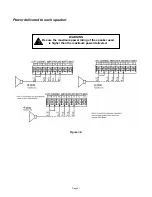
Страница 23: ...Page 21 Power delivered to each speaker WARNING Be sure the maximum power rating of the speaker used is higher than the maximum power delivered Figure 3 C ...

Страница 24: ...s and Outputs The Digital SyberSonic Pre Amplifier has five 5 sets of RCA type jacks Figure 4 C RCA Jacks Each set of RCA jacks has separate functions Main In This connection is the audio signal that is being fed directly from the Sound Card in the Core Unit Audio Output into the pre amplifier Fixed Out This connection is an unconditioned analog audio output from the Core unit BGM In This connecti...

Страница 25: ...Page 23 Section D Service Maintenance Routine Maintenance Schedule ...

Страница 26: ...rform a minimum of every 3 months if operating more than 14 hours per day operating where smoking is allowed or is otherwise in a dusty environment Perform a minimum of every 6 months if operated less than 14 hours per day and in a very clean environment You will need a new soft 2 paintbrush 1 Gently brush dirt from the cabinet cooling fans Verify fan operation 2 Brush dirt from the power supply f...

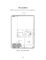
Страница 27: ...Page 25 Fan Locations NOTE The fan at the top of the front door is not shown in diagram below Figure 1 D Inside View of Cabinet ...

Страница 28: ...Page 26 Section E Parts Catalog Front Door Bill Acceptor Assemblies Inside and Outside Cabinet LCD Assembly Electronic Components Harnesses Accessories ...

Страница 29: ...Page 27 Front Door OUTSIDE VIEW 12 18 24 32 20 11 27 2 31 17 1 16 12 18 See Bill Acceptor Assemblies for parts details ...

Страница 30: ...Page 28 Front Door INSIDE VIEW ...

Страница 31: ...Page 29 Front Door INSIDE VIEW SHOWN WITHOUT BACK COVER LCD BRACKET ASSEMBLY 22 5 25 27 3 7 3 35 22 29 27 3 7 A SECTION A A A 27 20 8 32 11 29 1 24 29 7 17 27 22 7 12 ...

Страница 32: ...rusion Top Bottom 19 1 61195401 LCD Bracket Assembly 20 4 HW3252 Nut 10 24 Keps Hex 21 4 87841600 Nut 4 40 Keps Hex 22 16 87842300 Nut 6 32 Keps Hex MS 23 1 87843000 Nut 8 32 Hex MS Keps 24 1 61194601 Panel Front Door 25 3 80403003 Screw 8 32 X 3 16 PH PHMS S F 26 4 80443012 Screw 8 32 X 3 4 Hex WHM 27 31 80393007 Screw 8 32 X 7 16 FHPS 28 2 28277901 Screw M3 X 6 Phil Pan Head 29 34 80493008 Screw...

Страница 33: ... Mounting 5 1 22320201 Gasket Coinco B A 22316004 Dual Coinco Bill Acceptors 700 bill Ref Qty Part Description 1 2 22135614 B A Coinco Downstack 2 2 34098601 Bezel Coinco B A 3 1 34098801 B A Blockout 4 2 40981201 Bracket B A Mounting 5 2 22320201 Gasket Coinco B A 6 2 34022338 Dual B A Harness not shown 7 1 34100001 CBA Cover Assembly 22316002 Dual MEI Bill Acceptors 700 bill Ref Qty Part Descrip...

Страница 34: ...Page 32 Inside and Outside Cabinet INSIDE CABINET LOCK PARTS 26 25 23 22 24 ...

Страница 35: ...plifier 5 40982101 Power Supply 18 58679 Push Button Power 6 21581801 ATX Reset Button 19 58620 LF Power Cord 7 21581801 Router Reset Button 20 59953 LF Spool Aluminum 4 places 8 60820 LF Fan 2 places 21 59944 LF Wall Bracket 9 60809 A LF Fan Filter Housing 2 places 22 22321201 Lock Catch 2 pl 10 21895504 Fan Grill 2 places 23 34100601 Lock Arm 11 40982401 Fan Bracket 24 59363 Spring 12 22320701 P...

Страница 36: ...y Mounting Bracket 2 2 61194301 LED CBA Mounting Bracket 3 6 40976601 Inner LED Lights Circuit Board Assembly 4 2 40976602 Outer LED Lights Circuit Board Assembly 5 6 28254502 M4 X 10 Phil Pan Head Screw 6 24 70500004 Circuit Board Support 7 8 70500006 Circuit Board Support 8 1 61194701 32 Touchscreen Display 9 1 22212820 Ribbon Cable Assembly ...

Страница 37: ...et IEC 320 C 14 Components not shown above 4 1 70073618 Circuit Breaker 15 AMP 10 1 34099801 Power Supply Harness 5 1 30785704 Rocker Switch DPST 11 2 87843000 8 32 Keps Hex MS Nut 6 1 22135405 Jumper Plug 12 1 21963846 Wire Terminal Assembly 7 1 61195601 Power Supply Cover 13 2 21963845 Wire Terminal Assembly Pre Amplifier Assembly 70261 1A Ref Part Description 1 62004 A PCB Pre Amplifier 2 61184...

Страница 38: ...2 X Phil Pan Head inside cover 9 6 87842300 Keps Nut 6 32 3 2 80442304 Screw 6 32 X Hex WHS 10 1 40955703 Rowelink Controller Assembly 4 1 61992 LF Peripheral Interface Cover 11 1 58902 A LF Volume Control Harness 5 1 40981401 Peripheral Interface CBA 12 4 ST 11572 Thumbscrew for reference only not part of assembly 6 1 61973 A LF Rowelink Harness 7 2 80742304 Screw 6 32 X Sems Hex WHMS 13 1 AMI Ha...

Страница 39: ... C a b le 6 C o n d u cto r R e d 1 2 lo n g 7 A MP K EY P IN 7 Y E L LO W R E D Y E L L O W B L U E 1 0 0 P 1 4 R e d Ye l R e d O rg R e d B rn R e d W h t R e d G rn R e d B lk P 4 P 2 5 2 3 4 1 B rn W h t 3 6 7 5 4 1 2 3 1 2 5 6 W h ite 2 W H IT E B L A C K P 2 3 G R E E N R E D B la c k 2 B la c k 3 B lu W h t B la c k 1 2 3 4 1 W h ite 1 1 5 7 2 8 4 9 3 1 6 R e d S trip e To P in 1 B lu W h ...

Страница 40: ...en Y ello w 1 6 AW G U L AW M 3 0 0 V Stra n d ed 7 0 Lg Y e llo w 8 5 8 9 2 3 A LF 9 2 2 21 28 20 W hite B lac k R e d G re e n 5 6 2 0 6 0 A LF 6 2 0 5 9 A LF 7 6 2 0 0 9 A LF 6 205 9 A LF B lue 6 206 0 A LF 6 3 4 09 43 50 ...

Страница 41: ...Page 39 Harnesses 10 34022338 11 34022342 12 34033235 13 34037940 14 34100303 15 34099901 ...

Страница 42: ...4350 Peavey Audio Input Harness 7 62009 A LF Wired Volume Control Harness 24 8 58923 A LF Ground Strap 7 9 22212820 LED Board Interconnect Harness 10 34022338 Dual Bill Acceptor Harness 11 34022342 Single Bill Acceptor Harness 12 34033235 Ribbon Lighting Harness 13 34037940 ATX Reset Harness 14 34100303 Audio Output Assembly Harness 15 34099901 Peripheral Cabinet Harness 16 62002 A LF Ctr On Reset...

Страница 43: ...ol Cable ST 11327 2 8 x 1 1 2 Phillips Pan Head Screws for 2 Channel Remote 60608 A Lock Cam Ace Lock 62021 A Service Envelope contains the following 62022 Warranty Card ST 11149 Spade Connector ST 11572 4 Thumbscrew 6 32 x 1 4 Hard Drive Mounting 22200861 Small Parts Kit contains the following 89986124 4 Screw Lag 1 4 x 1 1 2 Hex Head ST 04565 D 8 32 x 1 Phillips Head Screw 86663614 8 x 7 8 Type ...

Страница 44: ...Page 42 Section F Troubleshooting LED Indicators Troubleshooting Chart Connection Diagrams Contact Information ...

Страница 45: ...on rate is more than 20 times per second CC RL TX LED Should be flashing Flashes when Rowelink Master Commands are sent from the Computer Core Appears almost continuously on rate is more than 20 times per second CRDT RL TX LED Should be flashing Flashes when the ROWELINK CONTROLLER sends a RL signal back to the CORE COMPUTER Rate is approximately once per second CRDT STATUS LED Will flash when a c...

Страница 46: ...e on but the application will not boot The system power supply or the LCD is defective or unplugged The LCD does not work The computer fan is on and all systems LEDs and lights are normal 1 The power plug video cable or LCD power supply wiring is not seated completely 2 The system power supply is defective 3 The LCD is dead The touchscreen does not work The application boots up but the touchscreen...

Страница 47: ... the router nothing happens 1 The AC power plug is not fully inserted in the receptacle on the back of the router 2 The wall plug is not hot The Link Act light on the front of the router does not light up when an Ethernet cable is plugged in the respective port 1 The Ethernet port is defective 2 The jukebox is not powered on 3 The cable is loose at the Core Computer in the jukebox Router does not ...

Страница 48: ...ete led GND 12V GND 12V GND 6V C C A A C A A C GND 12V 9V COM 9 VDC ROWELINK A ROWELINK B ON OFF CONTROL MUTENOT 58703 A BLY G R B W part of assy 70260 1A PERIPHERAL INTERFACE cba 61956 A 34099101 22164707 34033235 22140920 60842 2A LF 34099901 60820 LF 60820 LF B 2 B 3 40976601 D1 D2 D3 D4 D5 D6 D7 J1 D1 D2 D3 D4 D5 D6 D7 J2 J2 40976601 J1 J1 D1 D2 D3 D4 D5 D6 D7 J2 40976601 D1 D2 D3 D4 D5 D6 D7 ...

Страница 49: ...S 5V DC 12V DC IR RCV CC RL RX 24V DC ROWELINK ROWELINK DISCRETE WIRE ROWELINK ROWELINK ON OFF CONTROL MUTENOT 9V COM ROWELINK A ROWELINK B 9 VDC 9V COM 9 VDC ROWELINK A ROWELINK B ON OFF CONTROL MUTENOT SERVICE REJECT CALIBRATE POWER EVENT SW GROUND Y BL R Y R O R BR R W R B R G W 2 W 1 2 B 1 B 3 BL W BR W RLC part of assy 70260 1A cba 61135706 62045 A LF 61973 A LF 58902 A LF part of assy 70260 ...

Страница 50: ...SUP ROUTER MONITOR W CBA 34099701 POWER_SUPPLY_ASSY_40982101 GND L N 12V GND CTRL OUT EXT OUT MAIN IN OHMS 2 2 1 1 2 1 4 1 16 COM COM COM COM 1 16 1 4 1 2 1 2 2 J4 OHMS R CH L CH R CH L CH L R R L L R L R G R R B R W G W B R OUTPUT XFMR ASSY 70251 A 21121240 60905 1A LF 21121240 21121240 TO ROUTER ADAPTER SHEET 4 TO MONITOR SHEET 4 TO ATX PWR SUP SHEET 4 TO COMPUTER CORE AUDIO OUTPUT SHEET 4 TO PE...

Страница 51: ...B PORT GND 5VDC ROUTER AC ADAPTER SPAREPORT SPAREPORT SPAREPORT WIRELESS ETHERNET ROUTER 34037940 TO ISP PROVIDER PROVIDED BY CUSTOMER WHEN REQUIRED MODEM MODEM POWER ATX POWER SUPPLY 28280004 D LINK 4 PORT WBR 1310 62045 A LF TO ROWELINK CONTROLLER ASSY 40955703 P22 SHEET 2 ATX RESET TO PREAMP 70261 A L R INPUTS VIAHARNESS 62060 A LF SHEET 3 21121240 SUPPLIED WITH COMPONENT SHEET 4 34068708 61138...

Страница 52: ...sistance after contacting your distributor contact AMI Entertainment Network Inc USA and Canada call toll free 1 877 762 6765 1 877 ROC N ROL Outside the USA and Canada call 616 243 3633 E mail support amientertainment net www amientertainment com ...

Отзывы:

Похожие инструкции для Rock-Star Lx