Page 19
Connecting to Additional Power
Amplifiers or “House” Systems
To yield 3 or 4-zone mono or 2-zone stereo, the jukebox
may be connected to an additional power amplifier. To
do so, leave the amplifier inside the jukebox connected
to channels 1 and 2. The additional amplifier should be
connected to channels 3 and 4, powered by the signal
available at the EXT output RCA jacks. Volume will be
controlled via the IR Transmitter.
If the jukebox is to be connected to a House system that
will provide all of the amplification
and
volume control,
the House system may be fed with either the INT or EXT
output RCA jacks. After connecting to the house system,
set the Pre-Amp output to the desired maximum level
via the jukebox volume control. Then, disable the
jukebox volume control by accessing VCU Setup in the
Service Mode and unchecking the appropriate
channel(s). See the
Network Setup, Jukebox Operation,
Operator Setup Screens Manual
for details.
NOTE:
It is highly recommended that the “Fixed” output
or the direct output of the Core NOT be used to drive the
House system, unless that system contains ground loop
elimination circuitry and audio processing that will
compensate for a variation of signal level from one
selection to the next (AVC). These features are built into
the Pre-Amplifier, and they appear at the “INT” and
“EXT” outputs.
Pre-Amplifier Channel Assignments
INT Left
= Channel 1
INT Right = Channel 2
EXT Left = Channel 3
EXT Right = Channel 4
Connecting a Paging Microphone
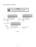
The Advanced SyberSonic Pre-Amplifier can accept
virtually any paging microphone. Pictured below are
wiring diagrams for the most common paging kits. The
necessary connector is included with a paging kit. To
use other paging kits, you will need to acquire one (1)
Amp part number 640250-4 housing (RMC P/N ST-
11244) and four (4) Amp part number 640252-1
contacts (RMC P/N ST-11245) or equivalent.
Rock-Ola® Yoga Microphone Kit
02379-01 02379-02
Rowe
®
NSM
®
Generic (Ground Switch to talk)
Connecting a Paging Microphone
The paging system works by either sensing audio on the
signal line, or by grounding pin 3 (switch). Whatever
microphone is used, it must have some kind of switch to
mute the audio when not in use.
Set the microphone gain switch to “LOW” and the gain
control at midpoint. Press the talk button on the
microphone and speak into it. The “Status” LED on the
amplifier should blink and the microphone signal should
be heard in the speakers. Adjust the microphone gain
control to the loudest level you want the location to be
able to use. If more gain is necessary, turn the
microphone gain switch to “HIGH”.
CAUTION: Be sure the gain control is turned down
to avoid speaker damage from acoustical feedback.
Refer to the amplifier settings for adjusting which
channels hear paging, the music level while paging, and
the length of time before the music comes back up.
1
2
3
4
Red
Black
Shield
Содержание Rock-Star Lx
Страница 1: ...22022611 Rev C Installation Owner s Manual ...
Страница 2: ......
Страница 25: ...Page 23 Section D Service Maintenance Routine Maintenance Schedule ...
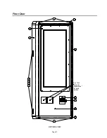
Страница 30: ...Page 28 Front Door INSIDE VIEW ...
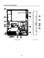
Страница 34: ...Page 32 Inside and Outside Cabinet INSIDE CABINET LOCK PARTS 26 25 23 22 24 ...
Страница 41: ...Page 39 Harnesses 10 34022338 11 34022342 12 34033235 13 34037940 14 34100303 15 34099901 ...
Страница 44: ...Page 42 Section F Troubleshooting LED Indicators Troubleshooting Chart Connection Diagrams Contact Information ...


