Asterion DC Multioutput ASA Series Operational Manual
M330516-01
3-69
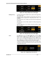
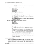
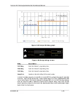
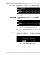
Pressing Exit button would return to Ramp Menu screen 2; Refer Figure 3-78.
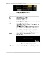
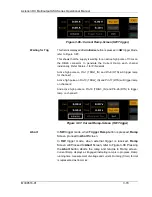
Figure 3-84: Current Ramp Screen
The Current Ramp menu has the following fields:
Entry
Description
Curr
Sets the start current for the ramp.
To Curr
Sets the end current for the ramp.
Volt
Sets the volt limit for the ramp.
Time
Sets the time in seconds to reach from start current to end current.
Trigger
Sets the trigger mode for the ramp.
In
SW (Software)
trigger mode, the ramp is generated as soon as the
Trigger Ramp button is pressed.
In
HW (Hardware)
trigger mode, the ramp will be generated when an
active high pulse of 10ms is applied on the DB26 connector respected
channel TRIG_IN pin; Refer Table 4-1 for PIN details.
Pin-1 (TRIG1_IN) and Pin-8 (RTN) to trigger ramp for channel 1,
Pin-10 (TRIG2_IN) and Pin-17 (RTN) to trigger ramp for channel 2,
And Pin-19 (TRIG3_IN) and pin-26 (RTN) to trigger ramp for channel 3.
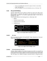
Initialize
Initializes the set Ramp parameters
.
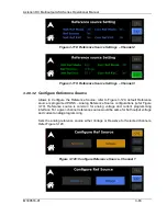
Refer to Figure 3-85
Press
OK
to
return.
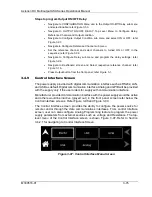
Figure 3-85: Ramp-Screen (Initialization)
Trigger Ramp
Generates the ramp in
SW
trigger mode. This will only be enabled after
Initialize
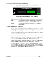
button is pressed, refer to Figure 3-86-:.


