Asterion DC Multioutput ASA Series Operational Manual
M330516-01
3-51
3.4.6.2
R
EMOTE
I
NHIBIT
External user interface (26 pin connector) provides with remote inhibit inputs for each
channel. A contact closure or direct short between remote inhibit terminal and return
will allows the Output of power supply to be turned ON.
The external user interface connector (26 pin connector) is supplied with a mating
connector which has the remote inhibit input output ON/OFF control signals for all the
3 channels connected (Pin-7 shorted to Pin-8 to enable channel-1, Pin-16 shorted to
Pin-17 to enable channel-2, Pin-25 shorted to Pin-26 to enable channel-3) to allow the
output to be enabled.
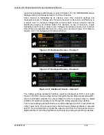
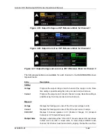
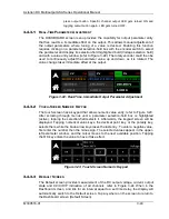
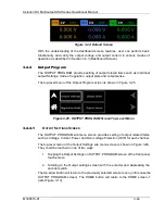
Remote inhibit can be configured in two modes (LIVE and LATCH), refer Figure 3-41.
Mode can be selected from the front panel remote inhibit screen. From the factory
default mode is LIVE. With this default factory setting (connected remote inhibit 26 pin
mating connector installed and the remote inhibit mode being LIVE), the user can turn
ON and OFF the power supply with the output switch.
User can remove the hardwired jumpers in the remote inhibit 26 pin female connector
and wire to a contact closure as per their requirement. User would need to select the
mode of remote inhibit using the front panel screen refer Figure 3-41, according to
their requirement of fault clearance.
Figure 3-41 shows the front panel screen for remote inhibit with channel-1 selected,
similarly user can select other channels and change the mode.
Figure 3-41: Remote Inhibit Screen channel 1
Figure 3-42: Remote Inhibit Screen channel 2
Figure 3-43: Remote Inhibit Screen channel 2

