Chapter Five : Advanced Serverboard Setup
73
VGA Enable/Disable
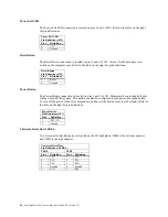
JPG1 allows you to enable or disable the VGA port. The default position is on pins 1 and 2 to
enable VGA.
LAN Enable/Disable
Change the setting of jumper JPL1 or JPL2 to enable or disable the onboard Ethernet (RJ45) ports
LAN1 and LAN2, respectively. The default setting is enabled.
Watch Dog Enable/Disable
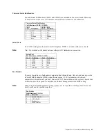
JWD controls the Watch Dog function. Watch Dog is a system monitor that can reboot the system
when a software application is “hung up”. Pins 1-2 will cause WD to reset the system if an
application is hung up. Pins 2-3 will generate a non-maskable interrupt signal for the application
that is hung up. Watch Dog must also be enabled in BIOS.
Power Force On Enable/Disable
Jumper JPF allows you to enable or disable the Power Force On function. If enabled, the power
will always stay on automatically. If this function is disabled (the normal setting), the user needs
to press the power button to power on the system.
Onboard Indicators
LAN1/LAN2 LEDs
The Ethernet ports (located beside the VGA port) have two LEDs. On each Gigabit LAN port, one
LED indicates activity when blinking while the other LED may be green, amber or off to indicate
the speed of the connection.
LE1
The LE1 LED located under the UID button is the UID indicator LED. LE1 illuminates when UID
is initiated either by the UID button or via IPMI. If initiated a second time, LE1 will turn off.
When the LED blinks blue it means the signal was initiated via IPMI. If blue continuously it
means a UID button initiated it.
PWR-LED
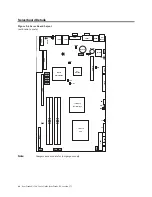
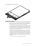
The PWR-LED is located next to the SEPC slot. Refer to the table on the right for indicator
definitions.
Содержание ManageTrends 2.7
Страница 18: ...StorTrends 1300 User s Guide StorTrends iTX version 2 7 xviii...
Страница 24: ...StorTrends 1300 User s Guide StorTrends iTX version 2 7 6...
Страница 33: ...Chapter Two Chassis Set Up 15 Accessing the Inside of the System...
Страница 45: ...Chapter Two Chassis Set Up 27 Do not close the window or click anywhere else until the operation completes...
Страница 59: ...Chapter Two Chassis Set Up 41 Step Seven All Done No Errors STOP YOU SHOULD NOW BE UP AND RUNNING...
Страница 60: ...StorTrends 1300 User s Guide StorTrends iTX version 2 7 42...
Страница 64: ...StorTrends 1300 User s Guide StorTrends iTX version 2 7 46...
Страница 70: ...StorTrends 1300 User s Guide StorTrends iTX version 2 7 52...
Страница 100: ...StorTrends 1300 User s Guide StorTrends iTX version 2 7 82...
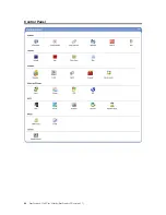
Страница 106: ...StorTrends 1300 User s Guide StorTrends iTX version 2 7 88 Control Panel...
Страница 236: ...StorTrends 1300 User s Guide StorTrends iTX version 2 7 218...
Страница 256: ...StorTrends 1300 User s Guide StorTrends iTX version 2 7 238...
Страница 277: ...Appendix E Replication Overview 259 Snap Assisted Replication Navigating with ManageTrends...
Страница 281: ...Appendix E Replication Overview 263 Replication SAR view Primary Box SAR view Secondary Box...
Страница 285: ...Appendix E Replication Overview 267 After Failover Operation in Secondary Box...
Страница 300: ...StorTrends 1300 User s Guide StorTrends iTX version 2 7 282...
Страница 308: ...StorTrends 1300 User s Guide StorTrends iTX version 2 7 290...
Страница 320: ...StorTrends 1300 User s Guide StorTrends iTX version 2 7 302 StorTrends Continuous Data Protection architecture...
Страница 330: ...StorTrends 1300 User s Guide StorTrends iTX version 2 7 312...
Страница 356: ...StorTrends 1300 User s Guide StorTrends iTX version 2 7 338...


