background image


Page 19 

200 Series 36V 

15312 


Throttle Switch 


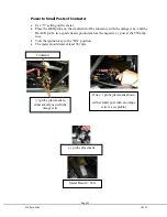
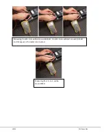
The throttle switch is an ON/OFF switch. 


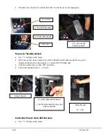
Use “Ω” setting on the meter. 


Remove the throttle harness connectors. 


Place one probe on each spade terminal on the Switch. 


With the button pushed in (throttle fully returned) the meter should say “OL”. 


With the button extended (throttle pressed), there should be a value shown close to 
Zero Ohms (0Ω). 


If this does not happen, replace the switch. 


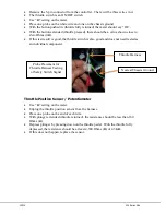
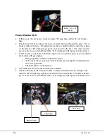
Throttle Position 

Sensor 

Probe Placement 

<160 Ω with 

throttle returned 

>4.3 KΩ with 

throttle depressed 

Содержание 36V 200 Series

Страница 1: ...15312 Service Manual 200 Series 36V...

Страница 2: ...es 4 Section 3 Motor and Controller 4 Motor removal and Installation 4 Motor Removal 4 Motor Installation 5 Controller Removal and Installation 5 Controller Removal 5 Controller Installation 5 Section...

Страница 3: ...Troubleshooting 16 Flowchart 16 Procedures 17 Throttle Harness Throttle Sensor Potentiometer Signal 17 Throttle Harness Throttle Switch Signal 17 Throttle Position Sensor Potentiometer 18 Throttle Swi...

Страница 4: ...h Track Width Front Rear 1160mm 47 7inch 1000mm 39 4inch Ground Clearance 170mm 6 7inch PERFORMANCE Motor Type 36V 300A Electric SepEx Output Power Torque 9 9 hp 7500rpm 13ft lbs 5500rpm Starting Keye...

Страница 5: ...ty or muddy areas require more frequent servicing Interval Initial service first week Monthly Quarterly Yearly Tire Pressure Wear p 2 I I Brake Fluid and Performance p 3 I I Chassis Nuts and Bolts p 3...

Страница 6: ...Ib ft N m Kg m Ib ft 4 1 2 0 1 0 2 0 7 1 5 1 5 3 0 15 0 3 1 0 2 0 5 1 4 0 2 0 4 1 5 3 0 3 6 0 3 0 6 2 0 4 5 6 4 7 0 4 0 7 3 0 5 0 8 12 0 8 1 2 6 0 8 5 8 10 16 1 0 1 6 7 0 11 5 18 28 1 8 2 8 13 0 20 0...

Страница 7: ...nting bolt tension and condition of insulating washers Clean motor with soapy water to allow proper cooling Batteries Clean surfaces of batteries with a solution of water and baking soda Inspect for d...

Страница 8: ...ttaching it to the mounting plate then remove the upper bolts Notice the order of washers as the bolts are removed 5 Carefully pull the motor away from the mounting plate allowing the drive pulley to...

Страница 9: ...4 Tighten the smaller 3 8 tensioner bolt to lock the tensioner in place It is not necessary to tighten the center nut on the tensioner but it may be tightened if desired or if tensioner slip is occur...

Страница 10: ...ndary drive belt by sliding it off of its pulley down the axle shaft to the left through the slot of the swingarm axle bracket and then off the axle 9 Install the new belt by sliding it over the axle...

Страница 11: ...cket Outward force may be applied to the clip to align with the holes 11 Carefully apply even pressure on the clip to insert it into the holes The sensor can get damaged if care is not taken here The...

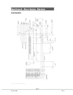
Страница 12: ...Page 9 200 Series 36V 15312 Section 6 ELECTRICAL SYSTEM SCHEMATICS Figure 1 Vehicle Schematic...

Страница 13: ...15312 200 Series 36V Figure 2 Motor Controller Schematic...

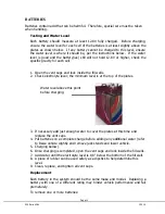
Страница 14: ...te level the minimum level is at the top of the plates 3 If necessary add just enough water to cover the plates at this time and replace the vent caps 4 Put batteries on a complete charge before addin...

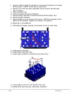
Страница 15: ...ts located underneath the battery rack 6 Remove battery hold down 7 Slide end battery out and remove from system NOTE the orientation of the battery as it is removed Repeat for all others to be replac...

Страница 16: ...d to jump the battery so charging can begin With the charger plugged in connect another external source such as a 12V dumb charger or a separate 12V battery to the terminals of the low voltage battery...

Страница 17: ...a voltage that is not relevant As batteries sit unused the voltage may creep up but the useable potential of the batteries is not there If the discharge meter is not resetting to full the charger shou...

Страница 18: ...Page 15 200 Series 36V 15312 Section 8 BRAKES BRAKE SYSTEM REPLACEMENT...

Страница 19: ...Check for 12V at Key Switch Red and Black on harness side Relay clicks once Check connections at Relay Ensure 12V at Black wire when key ON 36V at Orange Contactor wires Touch Pre charge Resistor If h...

Страница 20: ...ires in it Use setting on the meter Place one probe on the end of the gray wire and one on the end of the gray wire with the black stripe With plunger extended throttle returned the resistance should...

Страница 21: ...d the throttle switch is also good and does not need tested as an individual component Throttle Position Sensor Potentiometer Use setting on the meter Unplug the throttle position sensor from the harn...

Страница 22: ...one probe on each spade terminal on the Switch With the button pushed in throttle fully returned the meter should say OL With the button extended throttle pressed there should be a value shown close t...

Страница 23: ...or the models with gas engines o Chassis harness yellow plug inserted fully o Relay plug Blue or Black automotive relay o The dash panel harness especially the bullet connectors make sure they are tig...

Страница 24: ...ery It should read greater than 12 volts on each battery Battery Checks Battery System Use V setting on the meter Place one probe on the negative post at the 350 amp fuse Place the other on the positi...

Страница 25: ...and one probe to a good chassis ground such as the negative post at the 350 amp fuse Turn the ignition key to the ON position The meter should read 12 14 volts Controller Power from 36V Harness Use V...

Страница 26: ...t present check all connections and splices in the 36 volt harness and repair as necessary Wiring must be traced to locate the item that is disrupting the circuit Relay Make sure it makes a faint clic...

Страница 27: ...a blown fuse If still no power check all connections pins wires locations same as you would for the models with gas engines o Relay plug Blue or Black automotive relay o ALL pins at ALL connectors of...

Страница 28: ...e BLACK probe to a good chassis ground such as the negative post at the 350 amp fuse Turn the ignition key to the ON position The meter should read at least 36 volts Meter Result 36V One probe placeme...

Страница 29: ...Place the other at the controller s B position on the cable coming from the contactor It should read approximately 30 volts Action If the required voltage is not present wiring must be traced to locat...

Страница 30: ...d one on the other post The reading should be approximately 680 ohms If this does not happen replace the resistor Note Additionally a hot resistor across the Contactor indicates a failed controller Co...

Страница 31: ...15312 200 Series 36V Measuring from F to F will be around 9M Measuring from M to B will be around 18 25K From M to B will start around 18 25K and charge up as the meter is connected...

Отзывы: