


4 INSTALLATION INSTRUCTIONS
ADS32X TOUCH TRACKER with VIDEO MATRIX SWITCHER
8000-1691-02, Rev. A
Reviewing System Information
1. Press
Menu
.
2. Using the Tracker Ball, scroll down to
System Info
.
3. Press the zoom (line 1) or focus (line 2) button
to select the
System Info
menu option. The
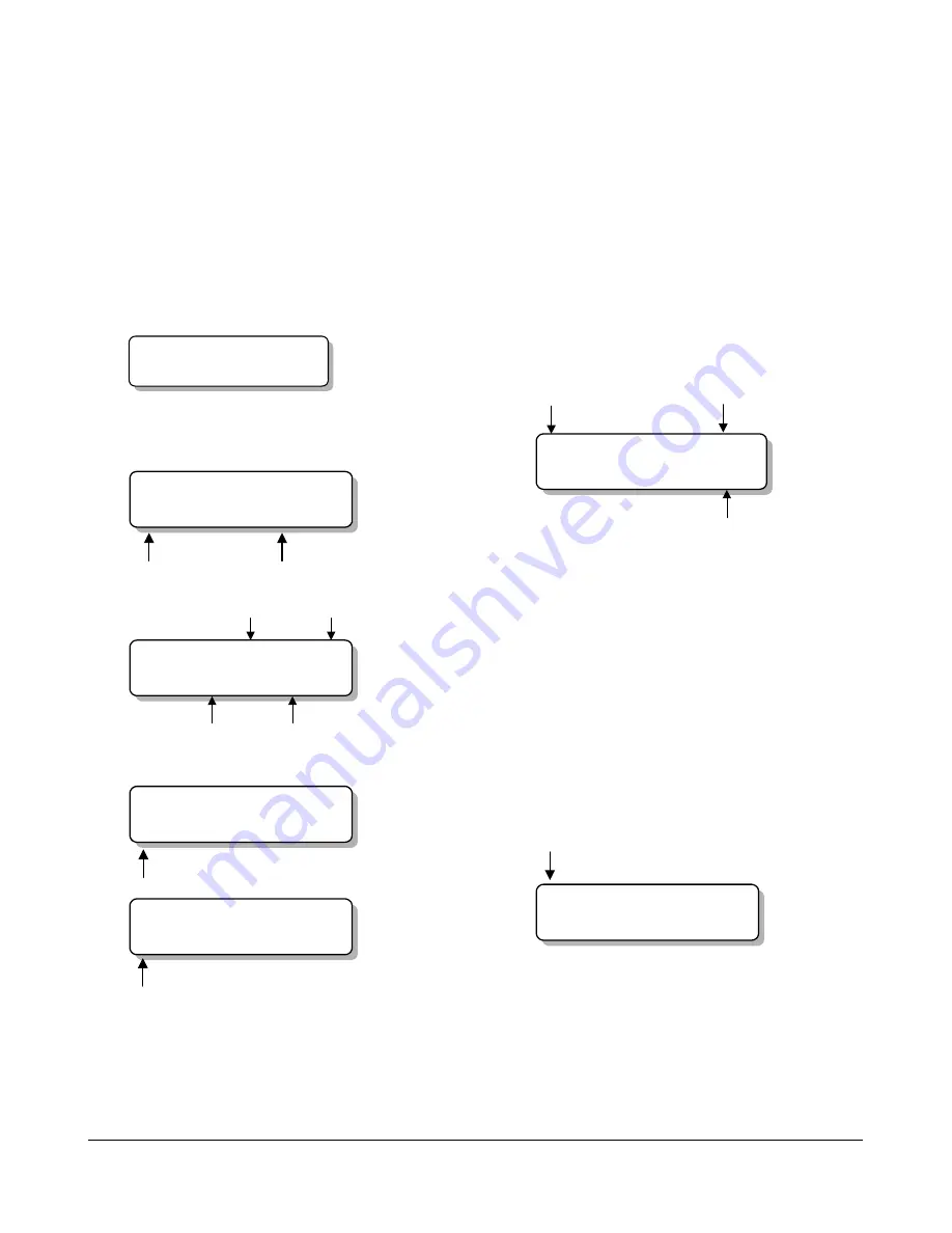
LCD screen displays the following message:
Primary/Secondary Indicator:
Primary Unit
<NEXT> <PREV>
4. Press
Next
to step through the following
messages:
Flash and EEPROM checksum values:
ROM Checksum
E=0A7B F=9C82
Flash
Checksum
EEPROM
Checksum
Tracker Ball calibration values:
Down
Min 63 60 61 60
Max D3 C3 C6 DE
Up
Left
Right
Flash and EEPROM part numbers (including
version):
Flash Part Number
and Version
Product Code
F 0701-0000-0000
Product Code
E 0701-0000-0000
EEPROM Part Number
and Version
5. Press
Menu
to exit.
Performing SensorNet Ping
Test
1. Use the number buttons to select a dome to
test, then press
Camera
.
2. Press
Menu
.
3. Using the Tracker Ball, scroll down to
Ping Dome/TTR
.
4. Press the zoom (line 1) or focus (line 2) button
to select the
Ping Dome/TTR
menu option
and to start the ping test on the selected
dome. The LCD screen displays the following
message:
*
=Device being
tested
No. of pings
transmitted
*Dome Tx=0006
TTR Bad=0002
No. of failed
responses
5. Press Next to perform the ping test on the
Secondary Touch Tracker controller unit.
6. Press
Menu
to exit.
Off-line domes or fixed cameras will generate a
warning beep and disallow use of the SensorNet
network test.
Changing the Port Setting
1. Press
Menu.
2. Using the Tracker Ball, scroll down to
Port Settings.
3. Press the zoom (line 1) or focus (line 2) button
to select the Port Settings menu option. The
LCD screen displays the following message:
*Operating Mode
Download Mode
*
=Selected mode
4. Press Next to change the currently selected
mode.
5. Press
Menu
to save the change and exit.


