background image

6    INSTALLATION INSTRUCTIONS

ADS32X TOUCH TRACKER with VIDEO MATRIX SWITCHER

8000-1691-02, Rev. A

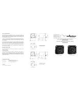
Figure 3.  VMS Wiring Diagram—Remote Switcher Location

5 2 3

RJ45

RJ45

RJ45

DB9 (M)

24 Vac A

Ground

24 Vac B

1

2

3

4

5

8

7

6

1

2

3

4

5

8

7

6

5 4 2

RJ45

RJ45

J1

J2

J3

EIM

5    4    3    2    1

1           3         5           7         9       11       13       15       17       19       21       23      25       27       29       31


2         4         6        8        10       12       14       16       18       20      22       24       26       28       31       32

1   2  3   4   5   6   7   8             SI      NO NC C

1           2            3          4            5

1             2             3

RS232 PORTS

MONITORS

ALARMS

RELAY

120V
60Hz

CAMERAS

Transformer

J3 Wiring

Pin

Function

1

N/A

2

24Vac A

3

Ground

4

24Vac B

5

N/A

DB9 (M) Wiring

Color

Pin

Function

Green

3

Receive

Red

2

Transmit

Orange

5

Ground

Touch Tracker

RJ45 Wiring

Color

Pin

Green

5

Red

4

Orange

2

Video Matrix Switcher

3-wire,
18AWG

Shield

EIM

Terminal

Box

Data
Cable

Modular
Cable

Modular
Cable

Ferrite
Core

Remote
Terminal
Box

120Vac, 60Hz or
240Vac, 50Hz

Содержание ADS32X

Страница 1: ...power transformer cable and the SensorNet data cable and if required the data cable to EIM 2 to the compression connector and connect it to J3 on each EIM 5 Wire the DB9 connector to the data cable Se...

Страница 2: ...OUCH TRACKER Secondary TOUCH TRACKER Video Matrix Switcher EIM DB9 M COLOR PIN FUNCTION Green 3 Receive Red 2 Transmit Orange 5 Ground NOTE The system supports up to 2 controllers Terminate E1 on the...

Страница 3: ...ss Next to toggle between using the primary unit for SensorNet polling and alarm monitoring or as the secondary unit with limited user functionality 5 Press Menu to reset the controller as a primary o...

Страница 4: ...sorNet Ping Test 1 Use the number buttons to select a dome to test then press Camera 2 Press Menu 3 Using the Tracker Ball scroll down to Ping Dome TTR 4 Press the zoom line 1 or focus line 2 button t...

Страница 5: ...ach EIM 7 Wire the DB9 connector to the data cable See the tables on page 2 Assemble the hood onto the DB9 connector 8 Connect the data cable to J1 on the EIM to the HP0047 terminal box 9 Install a fe...

Страница 6: ...1 2 4 6 8 10 12 14 16 18 20 22 24 26 28 31 32 1 2 3 4 5 6 7 8 SI NO NC C 1 2 3 4 5 1 2 3 RS232 PORTS MONITORS ALARMS RELAY 120V 60Hz CAMERAS Transformer J3 Wiring Pin Function 1 N A 2 24Vac A 3 Ground...

Страница 7: ...2 Alarm 1 3 Alarm 2 4 Alarm 3 5 Alarm 4 6 Alarm 5 7 Alarm 6 8 Alarm 7 9 Alarm 8 10 Ground 11 External Sync Ground 12 External Sync Input 13 Ground 14 Relay Normally Open 15 Relay Normally Closed 16 R...

Отзывы: