4211-195 05-22-12
Page 10
AI
SERIES STEAM BOILER WITH T100 CONTROL
INSTALLATION INSTRUCTIONS
IMPORTANT
:
The steam line should be pitched away from the boiler so any condensate will drain from the steam line. For best results, the boiler should
be installed as close to the steam room as possible, with its steam outlet valve higher than the steam heads in the steam room and the steam line run
straight to the steam heads with a pitch of at least ¼” per foot (6.4 mm per 305 mm) to drain into the room. Do not allow sags, dips or other low sections
in the steam line: these may block the steam fl ow or cause spitting of very hot water into the steam room.
As with any steam bath steam boiler, spitting, reduced steam and other problems can occur if too many elbows or tees are placed in the steam line, if the
line is too long, if the line has large rises or if there are low area or traps in the line. The effects depend on the number and size of these practices in a
particular installation.
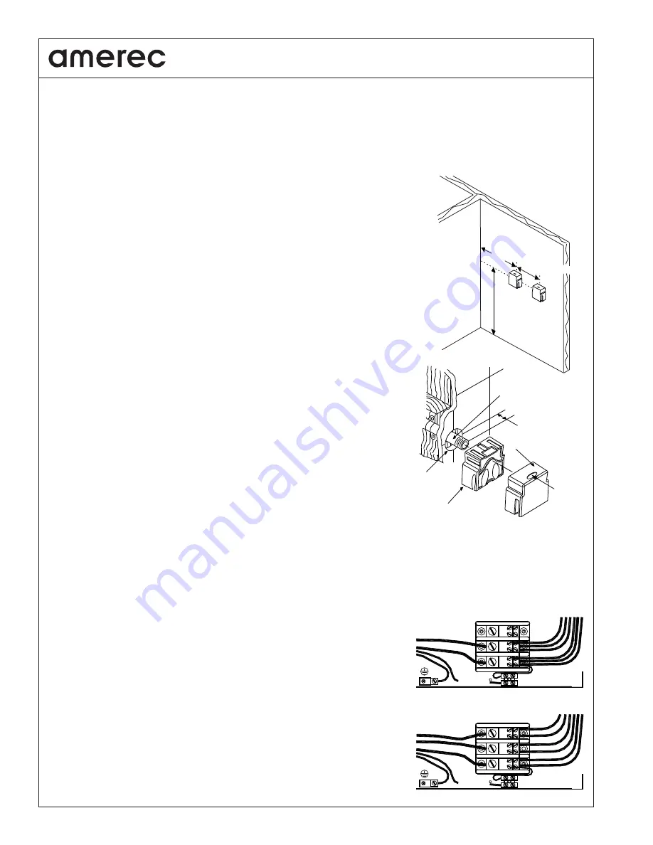
To reduce noise or improve the distribution of steam in larger rooms, additional steam heads may be
installed. Two steam heads are supplied with each boiler. Space steam heads at 6” (150 mm) intervals,
minimum. The steam heads should be located to ensure they do not discharge steam or drip condensate
where the user may come in contact with the hot moisture –
contact may cause injuries from scalding to
severe burns
!
AT THE STEAM ROOM: Drill/prepare a 1
3
/
8
" (35 mm) hole at each steam head location for steam line entry
15” to 18” (380 to 460 mm) above the
fl
oor. Terminate the steam line from the boiler with a tee at the steam
room then plumb each side of the tee to a steam head location and through the wall. Center the
3
/
4
” copper
steam pipe in the 1
3
/
8
” (35 mm) hole. Terminate the steam line with a
3
/
4
” NPT male adapter. Stub the line out
into the room
3
/
8
” (9.5 mm) from the
fi
nished surface. Secure the steam lines to structural members.
INSTALL STEAM HEAD INSULATOR(S): Fill in gaps using 100% Silicone caulk between steam pipe and
fi
nished wall surface at point of entry (
see drawing
). Apply silicone caulk to the
fi
nished wall side of the
steam head insulator and screw on hand tight until
fl
ush with the wall with the opening pointing down. If a
hand tight
fi
t does not align with the opening pointing down, use te
fl
on tape on the steam line threads to
adjust the
fi
t. Protect the steam head
fi
nish from damage while handling and tightening.
INSTALL STEAM HEAD: Slide the steam head on until it rests
fi
rmly against the
fi
nished wall. Tighten
the hex head screw underneath the steam head to secure it in place with the Allen
wrench provided. The steam head should be level with its fragrance reservoir at the top.
IMPORTANT Check all of the standard fi xtures in the steam room. All fi xture penetrations
and steam head insulators must be sealed with 100% silicone caulk to avoid moisture dam-
age within walls.
When the steam line is in an area where the temperature will be below 40°F (4.4°C) or if
the line is more than 20 feet (6 m) long, best results can be obtained by insulating the steam
pipe. Any insulation must be suitable for temperatures of at least 250°F (120°C).
3. INSTALL SAFETY VALVE LINE All AI boilers are equipped with a factory installed 15 psi ( 1.1 bar) pressure relief safety valve. This must be plumbed
to a ¾” indirect waste line. Do not install a shut off device in this line. Do not reduce this line. Do not form a trap in this line! Discharge from the safety
valve may be at over 240°F (120°C). Do not plumb this line into the steam room! Plumb this waste line per local plumbing codes.
4. INSTALL DRAIN All AI boilers are equipped with a factory installed manual ball valve to allow draining the tank. An optional electronic drain may be
installed after the manual valve. Plumb the drain to a ¾” indirect waste line. If the drain is opened while the boiler is under pressure, discharge
from the drain may be at over 240°F (120°C) and near 15 psi (1.1 bar). Do not plumb this line into
the steam room! Plumb this waste line per local plumbing codes. A (customer supplied) expansion
tank or blowdown cooling tank may be required by local code.
ELECTRICAL
Refer to the ID plate on the boiler’s switch panel to determine voltage and current requirements.
Electrical service for all models requires two (single phase) or three (3 phase) hot leads plus a suit-
able ground connection. Models operating on 208V, 240V, 415V or 480V also require a 14 AWG
Neutral for the boiler controls circuit. Models operating on 480V require a separate 120V (14AWG)
service for the controls circuit. Route the copper supply wire with appropriate strain relief through the
hole marked POWER ENTRIES. A multiple knockout is provided at this point for electrical service
using up to 2” conduit. A second knockout, ½” to ¾”, is provided for the 120V controls circuit, if needed.
CAUTION
:
Loose wire connections can cause heat damage to wires, terminal blocks and other
components and may void the warranty.
12in (300mm) MIN
15 to 18in
(380 to 460mm)
from nearest
surface
6in (150mm) min
L1
L2
L3
3-Phase Power
120V (240V~)
NEUTRAL
120V (240V~)
NEUTRAL
L1
L2
L3
1-Phase Power
3/8" (9.5 mm)
from wall
Steam Head Face
Fragrance
Reservoir
1-3/8" (35 mm)
Diameter hole
[fill gap with silicone]
3/4" NPT
Fitting
Steam Head Insulator
[seal back surfaces with silicone]


