4211-195 05-22-12
Page 16
AI
SERIES STEAM BOILER WITH T100 CONTROL
INSTALLATION INSTRUCTIONS
BLOWDOWN/AUTODRAIN (continued)
Failure to properly maintain the boiler can cause equipment failure and may void the warranty.
Using the Autodrain requires setting its clock or using the manual ELECTRONIC DRAIN switch on the boiler’s switch panel. Set the Drain Clock’s tabs
inward (so orange is showing) for the time of day you wish the boiler to drain. If the boiler also uses a Run Clock, a good time to drain the boiler is shortly
before the Run Clock is scheduled to start the generator for the day.
CAUTION
If draining a hot boiler, care must be taken to ensure it may drain safely
while unattended.
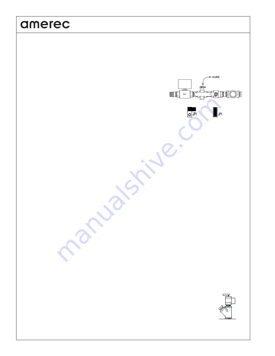
Note: The manual drain valve must be left open for the electronic drain to work properly and the
tank select jumper on the boiler’s circuit board must be positioned correctly to provide proper
drain cycle timing for the Autodrain™ system. If the jumper is mis-set, a 12-24kW boiler may
over
fi
ll and water may run out the steam head during the drain cycle or a 30-48kW boiler may
drain hot water.
The Autodrain’s™ system uses a computer controlled drain cycle to add and drain water in steps,
rinsing the tank and draining water at or below 140°F (60°C). This will also eliminate the need
for special drain systems or blowdown tanks in most jurisdictions. The drain cycle begins when
started by the Drain Clock,
fi
rst releasing any stored steam to the steam room then adding, mixing
and draining water a few times. Once the cycle is complete, the boiler returns to its normal
operation. If the steam bath operation when the Cooldrain™ cycle is started, the computer will wait until the room is up to temperature before beginning
the drain cycle in order to reduce the effects felt be the bathers. If the room does not come up to temperature within 20 minutes, the drain cycle will begin
anyway.
During the drain cycle, the upper Room Status LEDs will remain lit on the boiler. The lower Room Status LEDs and the Refresh switch LEDs will be off.
These LEDs will also blink to indicate slow draining and possible scale build up. This indicates that the boiler requires maintenance. The blinking will
continue until power to the boiler is reset.
Note: If the water drains too slowly, the upper Room Status LEDs will blink off once then light 5 seconds to indicate that the tank and drain may need
cleaning. The drain cycle will continue to operate normally. If the drain is nearly plugged, the upper Room Status LEDs will blink off twice then light 5
seconds to indicate that the drain is not functioning and servicing is necessary. The drain cycle will not operate again until power has been reset.
To manually drain the generator (with an electronic Autodrain installed)
set the ELECTRONIC DRAIN switch to the MANUAL OPEN position.
When an electronic drain is installed, make sure that the manual drain ball valve is always left in the open position.
Do not touch the safety valve when
the boiler is hot: the valve will be dangerously hot!
Open a steam valve or the safety valve to relieve the vacuum caused by draining. A more effec-
tive drain and rinse procedure is to:
• First set the HEAT switch to OFF then set the BOILER OPERATION switch to MANUAL RUN to start the boiler.
• Turn on the steam bath and verify the room’s steam valve is open (this will help the generator drain more quickly in the following steps). Adjust the
thermostat if needed to open the steam valve.
• Check the water level showing in the gauge glass: when the level rises above the middle of the gauge, the water valve should close.
• Set the ELECTRONIC DRAIN switch to the MANUAL OPEN position and set the FEEDWATER switch to STOP FILL to keep the water valve closed.
• Watch the water level in the gauge glass: allow the boiler to drain for at least 30 seconds after the level drops below the gauge glass for the
boiler to drain completely when clean. The water level should drop quickly and smoothly in a clean boiler.
• Toggle the ELECTRONIC DRAIN and FEEDWATER switches on and off as needed to add and drain water until it drains smoothly and quickly and
the water in the gauge glass is clear. A drain is provided on the bottom water gauge valve to allow draining the gauge glass assembly if needed.
• Reset all switches and the thermostat to their normal positions when done.
To manually drain the boiler (without an electrical Autodrain),
simply open the manual drain valve. The water draining from the boiler may cause a
vacuum, increasing the time needed to empty the boiler. To speed up the drain time, a room steam valve should be opened or the lever on the pop-off
safety valve may be raised to allow air into the boiler to eliminate the vacuum.
Do not touch the safety valve when the boiler is hot: the valve will be
dangerously hot!
When the boiler has
fi
nished draining, close the valves.
To rinse and drain the boiler, follow the autodrain procedure above, opening and closing the manual valve as needed.
CLEANING
A plugged port is provided next to the safety relief valve. This port is used to add cleaning solution to the boiler
without affecting other plumbing. The safety valve must be installed in the upright position as shown.
If the water drains slowly or sporadically, it may be necessary to remove the element assembly and clean the tank by hand. If this condition is seen, stop
using the boiler and call Technical Support for assistance.
30-48kW
Both Pins
12-24kW
One Pin


