D
ATA
F
ORMATS
NX2A4E2 User Manual
ADVANCED MICRO CONTROLS INC.
22
Output Data Formats (continued)
Dual Resolver Data Format (continued)
Setup Word 1
These bits are only acted upon when one, and only one, of the Channel Setup bits (bits 07 -04) of Word 0 is
set to “1”.
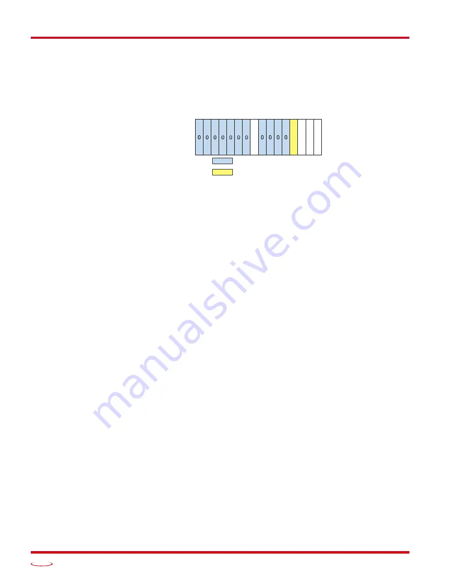
Figure R2.6 Single Turn Setup Word Format
Bit 08:
Enable ChLED –
This bit can be used to disable the channel’s front panel status LEDs. (The channel
itself remains active and transmits fault information to the host controller.) When this bit is a “0”, the
two channel LEDs are disabled. When this bit is set to “1”, the LED is active, and shows the state of
the channel. This bit is commonly used to disable the Status LED of unused channels.
Bit 03:
ResType –
This bit is only acted upon when programming channel 1. Setting this bit to “1” when pro-
gramming the second dual resolver channel will result in a Configuration Error response from the
NX2A4E2. When set to “0”, the NX2A4E2 configures itself to use AMCI transducers. When set to
“1”, the NX2A4E2 configures itself for transducers from Autotech or Gemco. When programmed for
Autotech or Gemco transducers, the Transducer Type parameter can only be programmed to 128.
Note that this bit can also be programmed when programming the single resolver channel 1.
Bit 02:
TachResponse –
This bit sets the Tachometer Response time for the channel. This is the time
between tachometer data updates. When set to “0”, the tachometer response time is set to 120 milli-
seconds. When set to “1”, the tachometer response time is set to 24 milliseconds.
Bit 01:
XFltLatch –
When set to “0”, the transducer fault latch is disabled. Transducer faults will clear them-
selves as soon as valid signals are detected on the channel’s inputs. When set to “1”, the transducer
fault latch is enabled. Transducer faults are latched, and can be cleared by issuing a programming
block with the Reset_Errors bit (Word 0: Bit 14), set to “1”.
Bit 00:
CountDir –
When the transducer is wired to the module as shown in this manual, set this bit to “0” for
CW increasing counts when looking at the transducer’s shaft. Set this bit to “1” for CCW increasing
counts. Note that count direction can also be switched by reversing pair connections on the transducer
input connector. Changing direction with wiring changes is covered in the Installation chapter of this
manual.
Transducer Type (Word 8)
This parameter sets the type of transducer attached to the module. This parameter is needed so that the mod-
ule can convert the two resolver positions into a single multi-turn value. The range of this parameter is the
discrete values of 100, 180, 1,000, 1,800, and 128. When the Resolver Type is set to ‘AMCI’, this parameter
can be programmed to 100, 180, 1,000, or 1,800. When the Resolver Type is set to ‘Autotech/Gemco’, this
parameter must be set to 128.
RESERVED: Bit must equal zero.
Setup Word (1)
15 14 13 12 11 10 09 08 07 06 05 04 03 02 01 00
XF
lt
La
tc
h
T
a
chR
e
s
p
ons
e
Re
s
T
y
p
e
Co
u
n
tD
ir
En
abl
e
_
C
hLE
D
Only when programming Channel 1.
Must be ‘0' for all other channels.
Содержание NEXUS NX2A4E2
Страница 1: ...MICRO CONTROLS INC ADVANCED U s e r M anual Manual 940 0N090 E2 Technology...
Страница 16: ...NX2A4E2 INTRODUCTION NX2A4E2 User Manual ADVANCED MICRO CONTROLS INC 16 Notes...
Страница 28: ...DATA FORMATS NX2A4E2 User Manual ADVANCED MICRO CONTROLS INC 28 Notes...
Страница 52: ...PROTOCOL SPECIFIC INFORMATION NX2A4E2 User Manual ADVANCED MICRO CONTROLS INC 52 Notes...
Страница 56: ...INSTALLING AN EDS FILE EtherNet IP Protocol ADVANCED MICRO CONTROLS INC 56 Notes...
Страница 66: ...ETHERNET IP EXPLICIT MESSAGING EtherNet IP Protocol ADVANCED MICRO CONTROLS INC 66 Notes...
Страница 70: ...MODBUS TCP CONFIGURATION Modbus TCP Protocol ADVANCED MICRO CONTROLS INC 70 Notes...
Страница 76: ...LEADERS IN ADVANCED CONTROL PRODUCTS ADVANCED MICRO CONTROLS INC...


