EN
4.2. Installing, Preparing and Operating the Ambu Visualization Device
Please refer to the Instruction for Use for the specific visualization device.
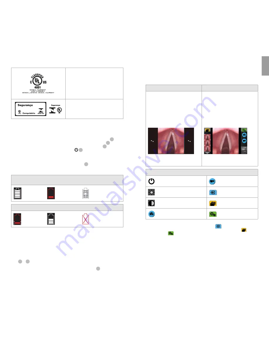
4.3. Operating the aView Monitor
Startup Image Mode
User Interface
Starts immediately after the power
button is pressed and continues
until the User Interface is loaded
(after approximately 1 min).
A live image is available and the User
Interface displays advanced user functions
(refer to the online aView User Guide on
www.ambu.com).
A live image from the plugged in Ambu
visualization device is available while aView
is loading. If no device is connected the
screen will be blue.
aView starts up in the Blue tab for Live Image
Viewing and recording live image.
The screen layout may vary depending on
the software version.
The screen layout may vary depending on
the software version.
Interface nomenclature
Power button
Video recording
Brightness adjustment
Viewing and recording
live image.
Contrast adjustment
Managing saved files.
Snap shot
System settings and User
Accounts.
Live image vs. recorded image
Round BLUE buttons are shown in the blue Live Image tab
and indicates a live image.
Square YELLOW or GREEN buttons are shown in the yellow File Management tab
and the
green Settings tab
and indicates a recorded image.
Battery status:
During start up, aView powers up and configures the visualization device.
If the aView battery icon on the screen changes from fully charged to low battery (red battery)
within 30 minutes, aView must be replaced.
Connection to external monitor
The image from an Ambu visualization device can be viewed on an external monitor using the
video out interface on aView. Connect the external monitor to the composite interface on the
right side of aView using the adaptor cable supplied (refer to the online aView User Guide on
www.ambu.com). Please consult the manual of the external monitor for further information on
how to connect an external video source by composite.
Medical — general medical equipment as to
electrical shock, fire and mechanical hazards
only in accordance with
ANSI/AAMI ES60601-1:2005/(R):2012
CAN/CSA-C22.2 No. 60601-1:08 (R2013)
IEC 60601-2-18:2009. UL60601-1, 1st ed.: 2006
CAN/CSA-C22.2 No. 601.1-M90, 2005
IEC 60601-2-18:1996. Control no 4UD1.
INMETRO Certificate Medical Electrical
Equipment
ABNT NBR IEC 60601-1,
ABNT NBR IEC 60601-1-2,
ABNT NBR IEC 60601-2-18.
4. Use of aView
Numbers in gray circles below refer to illustrations on page 2.
4.1. Preparation and Inspection of aView
1.
Closely examine aView and all parts for any damage (free from wear and tear)
1
.
2.
Place aView on a solid flat surface by using the stand on the back of aView
2a
.
If needed, aView can be placed on a pole by using the supplied bracket
2b
.
3.
Switch aView on by pressing the power button
3
. A white hourglass indicating that
aView is loading the User Interface will appear on the screen.
4.
Check the battery indicator on aView. A full charge lasts approximately 3 hours. Charge
the aView monitor if necessary by connecting the aView power supply to the wall socket
and insert the power plug into the power inlet of aView
4
. Make sure the power supply
is present and working at any time. It is recommended to locate the nearest wall socket
before start of the procedure.
The battery icon remains white until one block is left, after which it turns red.
When remaining battery capacity is 10% the red battery icon starts flashing.
Max. battery
status of
the aView
Min. battery
status of
the aView
Fully charged
battery still connected
to charger
Charging is shown with blocks flashing. Current capacity is shown with non-flashing blocks.
Battery is
charging
Battery current
capacity
Battery damaged
The power button will light up green when aView is turned ON and not connected to mains
and orange when aView is connected to mains. When aView is turned off, fully charged and
connected to mains the button will turn green.
If the battery is critically low, the recording functions will become unavailable.
If the aView is turned off and the battery is critically low, the power button will flash orange
five times every ten seconds to remind that charging is needed.
5.
Connect the selected Ambu visualization device to aView by plugging the cable connector
into the corresponding female connector on aView (push aside the rubber cover)
5a
or
5b
. Align the arrows on the visualisation device and aView before insertion.
6.
Verify that a live video image appears on the screen. Point the distal end of the Ambu
visualization device towards an object, e.g. the palm of your hand
6
.
7.
Adjust the image preferences on aView if necessary – please refer to the online extended
aView Instruction for Use on www.ambu.com for details.
8
9


