


38
ALUVISION > Clemence Dosschestraat 44 > 9800 Deinze, Belgium > T: +32 (0)9 381 54 70 > [email protected] > www.aluvision.com
Data output port 1 controls data flow 1, data output port 2 controls data flow 2.
The data flow in the software should always match the actual data flow of the
cabinets.
Attention: software is front view!
Configuring a screen using multiple data output ports can be done using the NovaLCT software, but is
also possible without (Novastar MCTRL660 or up).
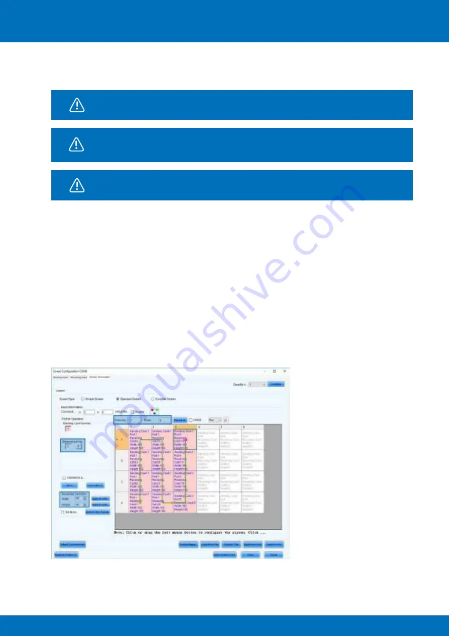
To configure the screen using the software, first open NovaLCT. In the ‘
Screen Configuration
’ window
select the third tab: ‘
Screen Connection
’ and select the second screen type option: ‘
Standard Screen
’.
Set the following data:
−
Columns
: 6, Rows: 4
−
Receiving Card Size:
192 x 192 pixels (since we’re using Hi-LED 55 2.5)
On the left side of the
‘Screen Configuration’
window you can choose which signal/data flow you want
to configure
(‘Ethernet port No’)
. The software automatically shows the correct amount of available
data output ports corresponding to the connected controller. The first data output port is automatically
selected.
With the first output selected, click the first cabinet from the first signal/data flow (bottom left, front view),
next click the cabinet above and continue by clicking all other cabinets in this flow (12) in a vertical way.
Select the second output
(‘Ethernet port No: 2’)
and click the first cabinet from the second signal/data
flow (bottom, 4
th
from the left). Next click the cabinet above and continue by clicking all other cabinets in
this flow (12) in a vertical way.


