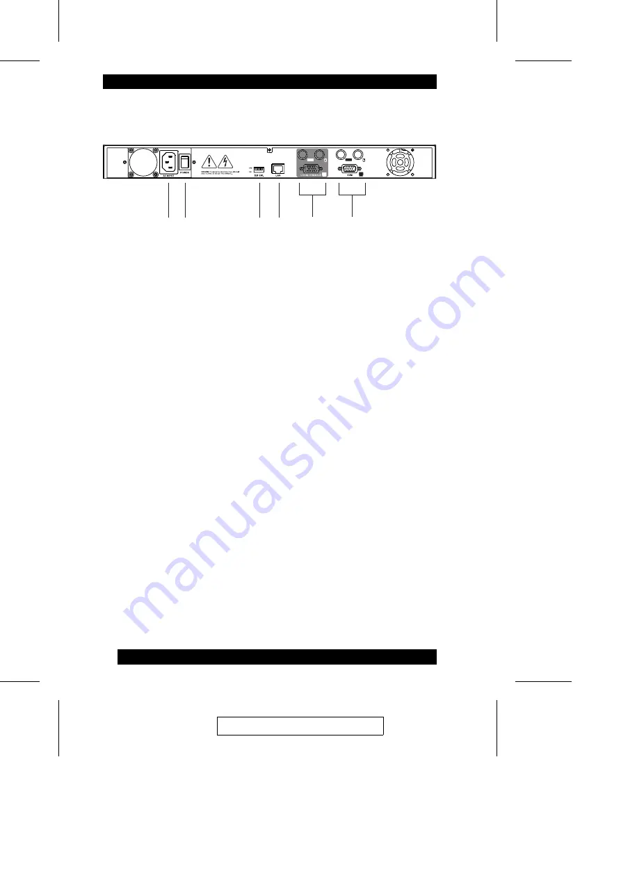
Rear Panel
1. Power Socket
The power cord to the AC source plugs in here.
2. Power Switch
This switch turns the KN9000 On and Off.
3. DIP Switch
The default setting for this switch is 1 OFF; 2 ON, 3 OFF; 4 OFF.
Segment 2 must be ON in order to save the changes made in the
Administration Utility (see Chapter 3). For security reasons, we strongly
recommend keeping Segment 2 OFF except for the times you make
Administration Utility changes.
4. RJ-45 Jack
The cable that connects the KN9000 to the Internet server plugs in here.
5. Local Console Port Section
The local administrator’s keyboard, monitor, and mouse plug in here. Each
port is indicated by an appropriate icon. The administrator can use this
console to access the server (or KVM switch) connected to the KN9000.
6. KVM Port Section
The KVM cable that links the KN9000 to the server or KVM switch tplugs in
here. Each port is indicated by an appropriate icon.
3
4
1
2
5
6
2004-05-04
6
Содержание KN9000
Страница 1: ...User Manual KN9000 2004 05 04...
Страница 4: ...2004 05 04 iv...
Страница 14: ...Notes 2004 05 04 4...
Страница 18: ...Notes 2004 05 04 8...
Страница 68: ...Notes 2004 05 04 58...
Страница 70: ...Notes 2004 05 04 60...


