38
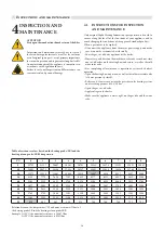
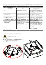
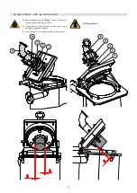
Inspections and maintenance
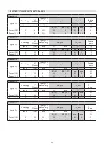
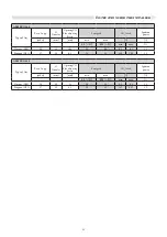
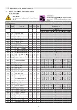
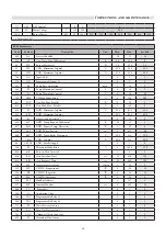
BMM parameters
Code
Symb.
Description
Unit Min. Max.
Factory settings
ARES PRO
150
230
300
348
400
500
600
803
Srv
Services Enabled
0
1
1
48
ChSet CH#1: Setpoint
°C
20
85
80
784
BC
Local BUS address
0
7
0
816
MI
ModBus Address
1
127
1
817
MT
Timeout Modbus
sec.
0
240
30
896
TU
°Fahrenheit
0
1
0
799
AC
Input 0/10V
0
2
0
376
DI1
Programmable Input #1
0
3
0
322
Po
Pump Post-circulation
min.
1
30
3
341
PL
Pump Minimum Control
%
0
100
30
313
Pr
Pump Maximum Control
%
0
100
100
31
HL
CH#1: Minimum Setpoint
°C
20
85
30
39
HH
CH#1: Maximum Setpoint
°C
20
85
85
792
CHP
CH: Max Modulation
%
0
100
100
619
IG
Ignition Modulation
%
30
80
50
35
45
45
45
40
35
(33)
527
PU
Fan: Pul./Rev
0
3
2
2
3
3
3
3
3
486
FP
Fan: Reg. Prop.
0
50
30
30
25
25
25
25
25
487
FI
Fan: Reg. Int.
0
50
9
9
25
25
25
25
25
489
Fpl
Fan: PWM min.
%
5
15
8
337
Fr
Modulation gradient
%
1.0
100.0
1.5
526
FU
Fan: Speed Max.
Hz
50
120
99
(94)
86
(82)
83
(81)
67
(64)
76
(69)
88
(83)
88
(92)
319
FH
Maximum Modulation
%
1.0
100.0
100
346
FL
Minimum Modulation
%
1.0
100.0
31
(31)
32
(32)
32
(32)
34
(34)
32
(36)
32
(33)
29
(30)
314
Sb
Standby Modulation
%
0
100
0
620
IP
Postpurge: Fan
%
0
100
65
617
IGL
Ignition: Mod. Min.
%
0
100
30
30
30
30
30
(36)
30
(34)
30
(29)
618
IGH
Ignition: Mod. Max.
%
0
100
80
80
74
54
54
45
40
353
HP
CH PID: Proportional
°K
0
50
25
354
HI
CH PID: Integrative
0
50
12
478
Hd
CH PID: Derivative
0
50
0
34
HY
Burner Hysteresis
°K
5.0
20.0
5.0
336
HS
Temperature Gradient
°C/min
0
30
5
483
rP
Gen: Temp. M
ax Diff
erential
°C
0.0
50.0
0.0
380
Al1
Programmable Sensor #1
0
2
0
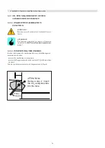
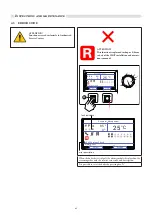
4.3 PROGRAMMING THE OPERATION
PARAMETERS
ATTENTION!
Function reserved exclusively to Authorised Service
Centres.
ATTENTION!
This
function is explained in chapter 8 (Device man-
agement) of the HSCP installation and maintenance
manual.
Содержание ARES Pro 150
Страница 2: ......
Страница 43: ...43 Inspections and maintenance ...

