17 / 55
5
LMU COM Port (CAN)
15
AC Switch (For AC Auxiliary In-
put)
6
16
LCD Screen
7
COM Port Reserved
17
LED Indicator
8
LAN COM Port
18
External Dispatch COM Port
9
INV + / INV -
19
EMS Meter Communication Port
10
Earthing Point X 2 (Required to con-
nect with grounding copper)
20
INV COM Port
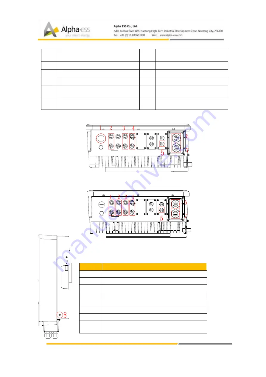
1.4.3
Inverter Cable Box
Figure 11 Inverter (DE)
Figure 8 Inverter (AU)
Item
Description (DE)
1
DC Switch
2
PV2
3
PV1
4
B/-
5
EMS COM port
6
On-Grid Wiring Ports
7
Back Up Wiring Ports
8
Earthing Point X 2 (Required To Connect With
Grounding Copper)


