8
5.1.2 Path measurement
The whole traverse path (405mm) of the drive gets suspended in 1.687.500 steps. This corresponds to
an intern resolution of 0,24µm, the change of the position in single steps gets indicated with a
resolution of 0,01mm. As both the load cell and the machine itself get expanded or compressed under
load, the absolute traverse deviates from the actual path on the measuring axle. To compensate this
error, the indicated path gets corrected with a force depending factor. Before the purchase of the
instrument, the correction factor gets appraised and setted by the manufacturer. The correction factor is
simple user appraisable and can be saved within the instrument.
A calibration (adjusting) should be effected after changing the force gauge as only theoratical values get
get adopted into the control unit during the initiation of the force gauge. The calibration takes place in
the service menu. (see chapter 6.2).
5.1.3 Disconnect conditions / Limits
Indipendent of the mechanical structur of the universal test stand and the force gauge, for which limits
get deposited before commissioning the instrument, it is possible to deposit universally valid limits for
path and force, as protection of checking tools and of material, which is to control. When these values
get achieved, the inspection process gets aborted and an infotext-display takes place in the lower line
of the display.
The load cells have an additional electronic overload protection which takes effect, independently of
the setted limits, as soon as a damage of the load cell is imminent. The control unit tries automatically
to take it off into the diametrical direction with a propulsion command.
Similarly the drive does not allow to cross the mechanical boarders which are predetermined by the
cursors, as they effect a emergency-stop.
Whenever an emergency-stop has been effected or the test stand does not allow any manual propulsion
because of overlapping limits, the test stand has to be turned currentless. In this condition the retention
force of the motor gets lifted and the load cell can be pushed to any position between the two cursors.
5.2. Manual mode
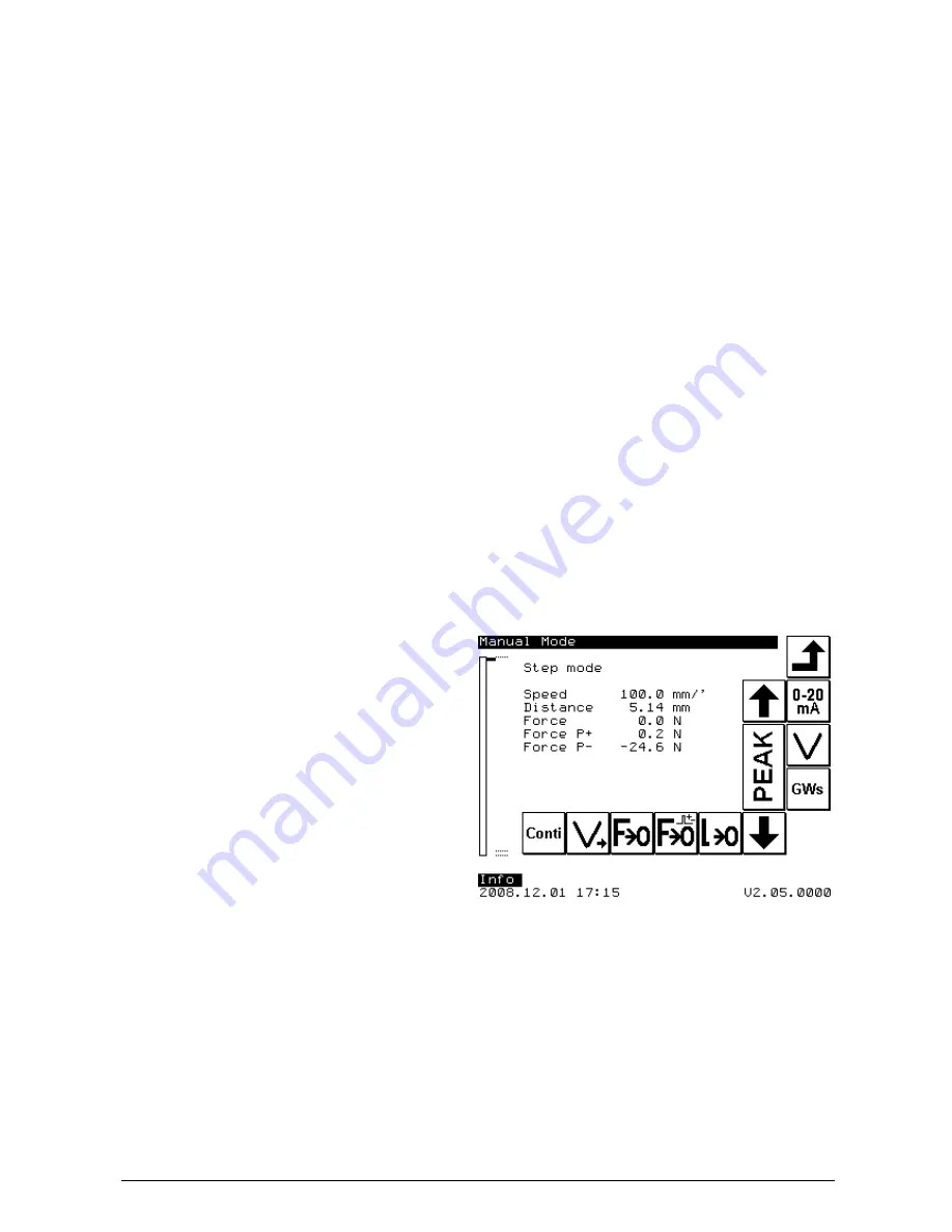
In the manual mode you can move the load cell
with
a
preselected
speed
within
the
predetermined limits upwards or downwards by
pressing the appropriate buttons. The current
reading and the current running speed are
indicated on the screen.
5.2.1 Regulation of the speed levels
In the manual mode up to 5 different speed levels can be chosen by pressing the key V
>
. The speed
levels 1 to 5 can be regulated within the therefore intended submenus. The submenu gets called by
pressing the key V
set
. Than you can choose the speed level you’d like to edit and enter the approriate
speed. When you leave the submenu, the speed levels get changed corrispondingly.


