x310 Series Installation Guide for Stand-alone Switches
41
Switch ID LED
The Switch ID LED, shown in Figure 12, displays the ID number of the
switch. A stand-alone switch has the ID number 0. Switches in a VCStack
have the numbers 1 to 4. Chapter 6, “Powering On the Switch” on page 93
has the procedure for verifying and, if necessary, changing the ID number
of the switch.
Figure 12. Switch ID LED
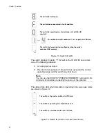
The states of the LED when the switch is not operating in the low power
mode are shown in Figure 13 on page 42.
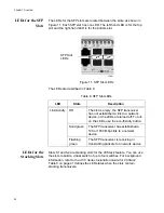
Table 9. S1 and S2 Slot LEDs
LED
State
Description
Link/Activity
Off
The slot is empty, the stacking transceiver
has not established a link to a network
device, or the LEDs are turned off. To turn
on the LEDs, use the eco-friendly button.
Solid green
The stacking transceiver has established
a link to another switch in the stack.
Flashing
green
The stacking transceiver is receiving or
transmitting packets.
Switch ID LED
Содержание AT-x310-26FP
Страница 10: ...Tables 10 ...
Страница 14: ...Preface 14 ...
Страница 46: ...Chapter 1 Overview 46 ...
Страница 56: ...Chapter 2 Beginning the Installation 56 ...
Страница 92: ...Chapter 5 Cabling the Networking Ports 92 ...
Страница 106: ...Chapter 6 Powering On the Switch 106 ...
Страница 116: ...Appendix A Technical Specifications 116 ...


