x310 Series Installation Guide for Stand-alone Switches
83
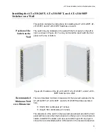
4. Place the switch on a table or desk.
5. Use a drill and a 1/4” carbide drill bit to pre-drill the two holes you
marked in step 3. Please review the following guidelines:
Prior to drilling, set the drill to hammer and rotation mode. The
modes break up the concrete and clean out the hole.
Allied Telesis recommends cleaning out the holes with a brush or
compressed air.
6. Insert the two anchors into the holes.
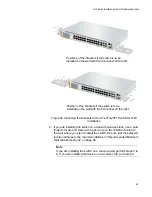
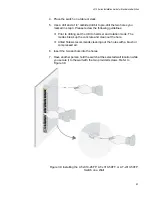
7. Have another person hold the switch at the selected wall location while
you secure it to the wall with the two provided screws. Refer to
Figure 39.
Figure 39. Installing the AT-x310-26FP, AT-x310-50FT, or AT-x310-50FP
Switch on a Wall
Содержание AT-x310-26FP
Страница 10: ...Tables 10 ...
Страница 14: ...Preface 14 ...
Страница 46: ...Chapter 1 Overview 46 ...
Страница 56: ...Chapter 2 Beginning the Installation 56 ...
Страница 92: ...Chapter 5 Cabling the Networking Ports 92 ...
Страница 106: ...Chapter 6 Powering On the Switch 106 ...
Страница 116: ...Appendix A Technical Specifications 116 ...

