


7
Figures
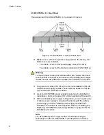
Figure 1: AT-DC2552XS / L3 Front Panel ............................................................................................................................19
Figure 2: AT-DC2552XS / L3 Rear Panel View....................................................................................................................22
Figure 3: SFP+ Slot LEDs ....................................................................................................................................................24
Figure 4: QSFP+ LEDs.........................................................................................................................................................25
Figure 5: Power/Fault LED ...................................................................................................................................................26
Figure 6: NET MGMT LEDs..................................................................................................................................................27
Figure 7: FAN Status LEDs ..................................................................................................................................................28
Figure 8: AC Power LED ......................................................................................................................................................29
Figure 9: AT-PWR06 Power Supply Module ........................................................................................................................31
Figure 10: AT-FAN06 Fan Module........................................................................................................................................33
Figure 11: Stacking Ports .....................................................................................................................................................37
Figure 12: AT-DC2552XS / L3 Stacking Configuration Example..........................................................................................38
Figure 13: VCStack Resilient Stacked Topology Example ...................................................................................................39
Figure 14: Resiliency Link Connecting to Switch Ports Over the Resiliency Link VLAN ......................................................40
Figure 15: Resiliency Link Connecting to Switch Ports Over the Resiliency Link VLAN Using a Network Hub ...................41
Figure 16: Stacking Ports .....................................................................................................................................................42
Figure 17: Contents of the AT-DC2552XS / L3 Shipping Box ..............................................................................................52
Figure 18: Contents of the AT-PWR06 Power Supply Module Shipping Box.......................................................................53
Figure 19: Contents of the AT-FAN06 Fan Module Shipping Box ........................................................................................54
Figure 20: Attaching the Rubber Feet ..................................................................................................................................56
Figure 21: Possible Bracket Locations .................................................................................................................................57
Figure 22: Attaching the Brackets to Switch.........................................................................................................................58
Figure 23: Mounting the Switch in an Equipment Rack ........................................................................................................59
Figure 24: Loosen Power Supply Captive Screws................................................................................................................60
Figure 25: Insert AT-PWR06 Module Into Chassis...............................................................................................................61
Figure 26: Tighten AT-PWR06 Captive Screws ...................................................................................................................62
Figure 27: Loosen Screws on Fan Blank Cover ...................................................................................................................64
Figure 28: Insert AT-FAN06 Module Into Chassis ................................................................................................................64
Figure 29: Tighten AT-FAN06 Captive Screws.....................................................................................................................65
Figure 30: Removing the Dust Plug from an SFP+ Slot .......................................................................................................69
Figure 31: Handle on SFP Transceiver ................................................................................................................................69
Figure 32: Installing an SFP+ Transceiver ...........................................................................................................................70
Figure 33: Removing SFP+ Dust Cover ...............................................................................................................................70
Figure 34: Attaching a Fiber Optic Cable to an SFP+ Transceiver.......................................................................................71
Figure 35: Removing the Dust Plug from an SFP+ Slot .......................................................................................................71
Figure 36: Installing an SFP+ Direct Attach Cable ...............................................................................................................72
Figure 37: Removing QSFP+ Slot Dust Cover .....................................................................................................................74
Figure 38: Installing a QSFP+ Transceiver...........................................................................................................................74
Figure 39: Removing QSFP+ Dust Cover ............................................................................................................................75
Figure 40: Attaching a Fiber Optic Cable to a QSFP+ Transceiver......................................................................................75
Figure 41: Removing QSFP+ Slot Dust Cover .....................................................................................................................76
Figure 42: Installing a QSFP+ MTHTP Cable.......................................................................................................................76
Figure 43: Connecting the Management Cable to the Console Port ....................................................................................82
Figure 44: Connecting the Twisted Pair Cable into the NET MGMT port .............................................................................85
Figure 45: USB Console Connector and Port Pin Layout.....................................................................................................93
Figure 46: RJ-45 Connector and Port Pin Layout.................................................................................................................94
Содержание AT-DC2552XS
Страница 1: ...613 002097 Rev A AT DC2552XS L3 ENTERPRISE CORE SWITCH Installation Guide...
Страница 8: ...Figures 8...
Страница 10: ...Tables 10...
Страница 14: ...Preface 14...
Страница 34: ...Chapter 1 Overview 34...
Страница 44: ...Chapter 2 VCStack Overview 44...
Страница 86: ...Chapter 7 Managing the Switch 86...
Страница 90: ...Chapter 8 Troubleshooting 90...
Страница 96: ...Appendix A Technical Specifications 96...