


Chapter 1: Overview
20
Note
Each SFP+ slot has a dust cover installed at the factory which
should be left in place until an SFP+ transceiver is installed.
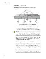
SFP+ Slot LEDs - Each SFP+ slot has a corresponding LED which
displays the link and activity status of the port. See Figure 3 on
page 24 for the location of these LEDs and Table 2 on page 24 for
their functional description.
QSFP+ Slots - There are four QSFP+ slots which support
communication speeds up to 40 GB. These slots are numbered 49,
53, 57 and 61. Each slot may be configured as one 40 GB port or 4
X 10GB ports in the management software. See Figure 4 on page
25 for the location of these LEDs and Table 3 on page 25 for their
functional description. Refer to “Installing QSFP+ Transceivers and
Cables” on page 73 for installation instructions.
Note
Each QSFP+ slot has a dust cover installed at the factory which
should be left in place until a QSFP+ transceiver is installed.
Note
QSFP+ transceivers must be purchased separately. For more
information about the list of supported QSFP+ transceivers, refer to
“Optional SFP+ Transceivers” on page 17.
QSFP+ Slot LEDs - Each QSFP+ slot has a corresponding QSFP+
LED which displays the link and activity status of the QSFP + slots.
Refer to “QSFP+ Slot LEDs” on page 25 for the functional
description.
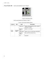
Power/Fault LED - The Status LED displays the overall status of
the chassis, power supply modules and fan modules. Refer to
“Power/Fault LED” on page 26 for the functional description.
Console Port - The console port is a standard RS-232 interface
using an USB interface. This port provides the capability to
manage the configuration and firmware of the switch locally
independent from the Ethernet network. Refer to “Connecting the
Console Port” on page 82 for more information.
Note
An RS-232 cable (female USB / D-Sub 9 pin) cable is included with
the AT-DC2552XS / L3 shipping container.
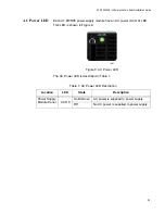
NET MGMT Port - This 10/100/1000BASE-T RJ-45 Ethernet port
provides the capability to manage the configuration and firmware
of the switch. You can obtain or forward information via the
Содержание AT-DC2552XS
Страница 1: ...613 002097 Rev A AT DC2552XS L3 ENTERPRISE CORE SWITCH Installation Guide...
Страница 8: ...Figures 8...
Страница 10: ...Tables 10...
Страница 14: ...Preface 14...
Страница 34: ...Chapter 1 Overview 34...
Страница 44: ...Chapter 2 VCStack Overview 44...
Страница 86: ...Chapter 7 Managing the Switch 86...
Страница 90: ...Chapter 8 Troubleshooting 90...
Страница 96: ...Appendix A Technical Specifications 96...