


AT-DC2552XS / L3 Enterprise Core Switch Installation Guide
23
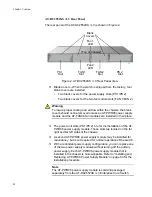
The fan module slots (FAN 1/FAN 2) are for the installation of the
AT-FAN06 fan module. These slots are located on the center right
and center left of the chassis.
Two AT-FAN06 fan modules are required in the chassis for normal
operation of the switch. Refer to “Installing and Replacing AT-
FAN06 Fan Module” on page 64 for the installation procedure.
Note
The AT-FAN06 fan module is sold and packaged separately from
the AT-DC2552XS / L3 Enterprise Core Switch.
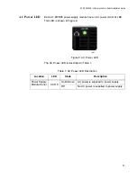
Fan LEDs - The fan LEDs FAN 1 (upper LED) / FAN 2 (lower LED)
display the status of the fan modules. They are located in the
center of the chassis between the fan module slots. Refer to
Table 6 on page 28 for the functional description of these LEDs.
Содержание AT-DC2552XS
Страница 1: ...613 002097 Rev A AT DC2552XS L3 ENTERPRISE CORE SWITCH Installation Guide...
Страница 8: ...Figures 8...
Страница 10: ...Tables 10...
Страница 14: ...Preface 14...
Страница 34: ...Chapter 1 Overview 34...
Страница 44: ...Chapter 2 VCStack Overview 44...
Страница 86: ...Chapter 7 Managing the Switch 86...
Страница 90: ...Chapter 8 Troubleshooting 90...
Страница 96: ...Appendix A Technical Specifications 96...