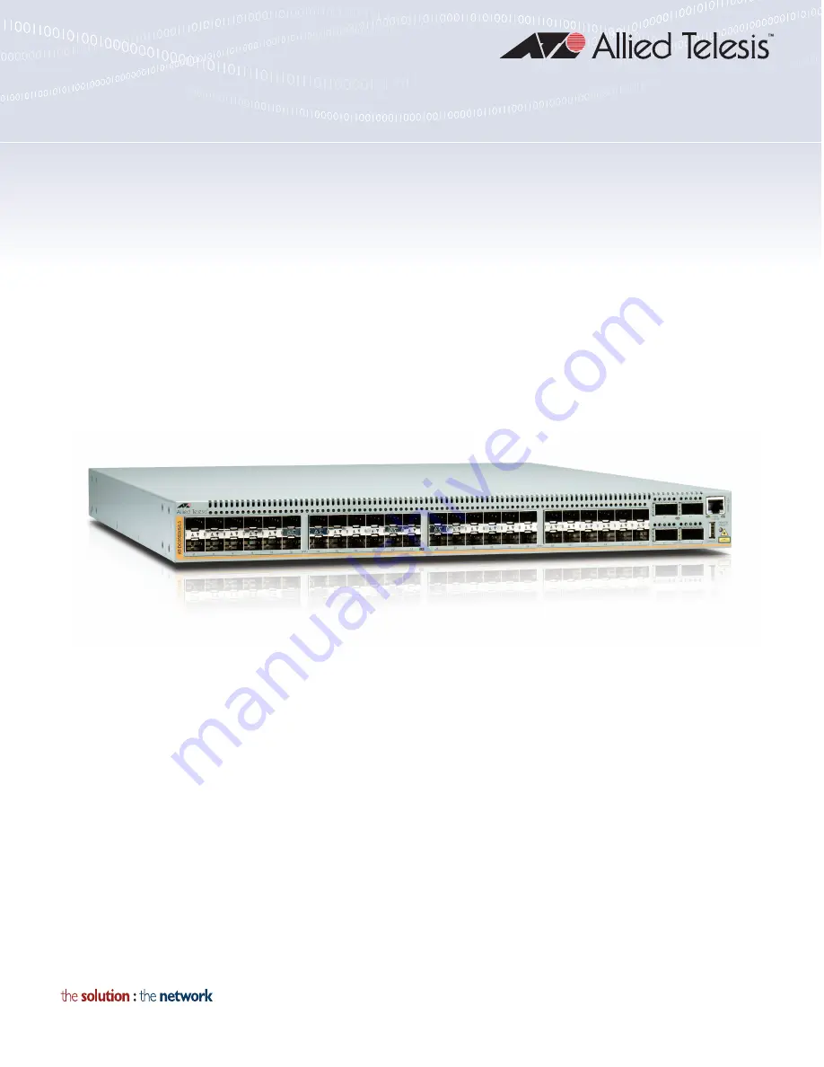
Allied Telesis AT-DC2552XS Скачать руководство пользователя страница 1

613-002097 Rev. A

AT-DC2552XS/L3

ENTERPRISE CORE SWITCH

Installation Guide

Содержание AT-DC2552XS

Страница 1: ...613 002097 Rev A AT DC2552XS L3 ENTERPRISE CORE SWITCH Installation Guide...

Страница 2: ...espective owners Allied Telesis Inc reserves the right to make changes in specifications and other information contained in this document without prior written notice The information provided herein i...

Страница 3: ...generates uses and can radiate radio frequency energy and if not installed and used in accordance with this instruction manual may cause harmful interference to radio communications Operation of this...

Страница 4: ...d Safety Statements Important The indicates that translations of the safety statement are available in the PDF document Translated Safety Statements posted on the Allied Telesis website at www alliedt...

Страница 5: ...on 42 The Role of the Stack Master 42 Chapter 3 Beginning the Installation 45 Installation Overview 46 Reviewing Safety Precautions 47 Planning the Installation 51 Unpacking the Switch 52 AT DC2552XS...

Страница 6: ...Powering On the Switch 78 Turning Off the Switch 80 Chapter 7 Managing the Switch 81 Local Management 82 Connecting the Console Port 82 Remote Network Management 84 NET MGMT Cable Installation 84 Chap...

Страница 7: ...58 Figure 23 Mounting the Switch in an Equipment Rack 59 Figure 24 Loosen Power Supply Captive Screws 60 Figure 25 Insert AT PWR06 Module Into Chassis 61 Figure 26 Tighten AT PWR06 Captive Screws 62...

Страница 8: ...Figures 8...

Страница 9: ...D Descriptions 28 Table 7 AC Power LED Description 29 Table 8 Installation Procedures 46 Table 9 SFP Cables 68 Table 10 QSFP Cables 73 Table 11 Product Dimensions 91 Table 12 Product Weights 91 Table...

Страница 10: ...Tables 10...

Страница 11: ...nstall the AT DC2552XS L3 Enterprise Core Switch and the associated power supply and fan modules on a desktop or in a 19 inch equipment rack This preface contains the following sections Document Conve...

Страница 12: ...tions Note Notes provide additional information Caution Cautions inform you that performing or omitting a specific action may result in equipment damage or loss of data Warning Warnings inform you tha...

Страница 13: ...ets to learn about RMAs and to contact Allied Telesis technical experts USA and EMEA phone support Select the phone number that best fits your location and customer type Hardware warranty information...

Страница 14: ...Preface 14...

Страница 15: ...pter 1 Overview This chapter contains the following sections AT DC2552XS L3 Features on page 16 LEDs on page 24 Console Port on page 30 AT PWR06 Power Supply Module on page 31 AT FAN06 Fan Module on p...

Страница 16: ...and management ports on the AT DC2552XS L3 48 SPF slots 4 QSFP slots 1 Console port USB 1 NET MGMT port RJ 45 Note Refer to Table 16 on page 93 for the Console connector pinout functions System Capac...

Страница 17: ...ay elect to install a second power supply module for redundancy Note The AT PWR06 power supply module and AT FAN06 fan module are sold separately from the AT DC2552XS L3 Enterprise Core Switch Contact...

Страница 18: ...ach Cable 1m AT QSFP3CU QSFP Direct Attach Cable 3m Fiber Optic Cable for AT QSFPSR ET3 MPO12 1 1m ET3 MPO12 5 5m Management Software and Interfaces Here are the management software and the management...

Страница 19: ...the exhaust air vents clear of any obstructions to insure proper cooling of the switch components SFP Slots There are 48 SPF slots ports 1 48 on the front panel Each port supports communication speed...

Страница 20: ...alled Note QSFP transceivers must be purchased separately For more information about the list of supported QSFP transceivers refer to Optional SFP Transceivers on page 17 QSFP Slot LEDs Each QSFP slot...

Страница 21: ...ion The cable requirements of the NET MGMT port are given in Table 1 Table 1 Twisted Pair Cable Specifications for the NET MGMT Port Cable Type 10Mbps 100Mbps 1000Mbps Standard TIA EIA 568 B compliant...

Страница 22: ...he installation of the AT PWR06 power supply module These slots are located on the far right and far left sides of the chassis A second AT PWR06 power supply module may be installed for redundancy but...

Страница 23: ...normal operation of the switch Refer to Installing and Replacing AT FAN06 Fan Module on page 64 for the installation procedure Note The AT FAN06 fan module is sold and packaged separately from the AT...

Страница 24: ...wer SFP slot These SFP slot LEDs are shown in Figure 3 Figure 3 SFP Slot LEDs The SFP slot LEDs are described in Table 2 Table 2 SFP Slot LED LED State Description Link Activity Solid green The SFP tr...

Страница 25: ...SFP LEDs The QSFP LED is described in Table 3 Table 3 QSFP LED LED State Description Link Activity Solid green The QSFP transceiver has established a link to a network device Flashing green The QSFP t...

Страница 26: ...scribed in Table 4 Table 4 Power Fault LED Description Location LED State Description Front Panel POWER FAULT Solid green Power is being supplied and the chassis is operating normally Flashing green S...

Страница 27: ...nt Panel ACT Right LED Solid green The NET MGMT port has established a link to a network device but no packets are being transmitted or received Flashing green The NET MGMT port is receiving or transm...

Страница 28: ...in Table 6 Table 6 FAN Status LED Descriptions Location LED State Description Rear Panel FAN1 top LED Solid Green Fan operating normally Solid Red Fan is in failure mode Off No power is supplied to th...

Страница 29: ...has an AC power AC OK LED This LED is shown in Figure 8 Figure 8 AC Power LED The AC Power LED is described in Table 7 Table 7 AC Power LED Description Location LED State Description Power Supply Modu...

Страница 30: ...ded with the switch Note Refer to Console Port Pinouts on page 93 for USB pin orientation and the signal functions assigned to each pin To establish a local management session with the switch connect...

Страница 31: ...power supply operates in a redundant state and is automatically activated by the switch if the active power supply loses power or fails The change over is instantaneous and has no effect on the Ether...

Страница 32: ...nts to cool the power supply and the chassis components The air is discharged through the exhaust air vents on the top of the chassis front panel See Figure 1 on page 19 for the location of the exhaus...

Страница 33: ...10 Figure 10 AT FAN06 Fan Module The components of the AT FAN06 fan module are as follows Captive screws The two captive screws secure the fan module to the chassis frame Handles The two handles are u...

Страница 34: ...Chapter 1 Overview 34...

Страница 35: ...35 Chapter 2 VCStack Overview The chapter contains the following sections VCStack Introduction on page 36 Stack Formation on page 42...

Страница 36: ...able to provide an alternative data path thus the stack will continue to function if a single switch fails Degraded performance might occur however due to the reduced VCStack bandwidth User ports can...

Страница 37: ...s QSFP ports 49 53 57 or 61 A stack always has a primary stack member called the stack master displayed in the show commands as the active master The remaining switch then becomes an ordinary member o...

Страница 38: ...e network connectivity uptime is a major criteria you can use virtual chassis stacking to create highly reliable network configurations The network shown in Figure 13 on page 39 employs redundant link...

Страница 39: ...tches are stacked and so appear as a single logical switch Note Smaller switches such as the AT DC2552XS L3 can be also be used to form the stacked core or stacked distribution This network topology s...

Страница 40: ...ports on both devices Once you have connected the cable you can run the STACK RESILIENCYLINK command to create the resiliency link Resiliency Link Configurations via Switch Ports Two resiliency link c...

Страница 41: ...DC2552XS L3 Enterprise Core Switch Installation Guide 41 Figure 15 Resiliency Link Connecting to Switch Ports Over the Resiliency Link VLAN Using a Network Hub DC2552XS L3 Switches DC2552XS L3 Switch...

Страница 42: ...QSFP port you are using This capability enables you to create a stack of 2 geographically separated switches as a single stack The Role of the Stack Master In addition to being a member of its VCStack...

Страница 43: ...ion scripts to match any changes you have made to the stack ID assignments Note The ability to independently set both a stack member s priority and its ID means that the stack master does not need to...

Страница 44: ...Chapter 2 VCStack Overview 44...

Страница 45: ...Beginning the Installation The chapter contains the following sections Installation Overview on page 46 Reviewing Safety Precautions on page 47 Planning the Installation on page 51 Unpacking the Switc...

Страница 46: ...eviewing Safety Precautions on page 47 2 Planning the Installation on page 51 3 Unpacking the Switch on page 52 4 Installing the Switch on a Desktop on page 56 OR Installing the Switch in an Equipment...

Страница 47: ...stare into the laser beam L2 Warning Do not look directly at the fiber optic cable ends or inspect the cable ends with an optical lens L6 Warning To prevent electric shock do not remove the cover No...

Страница 48: ...s on accessible metal parts E4 Note Pluggable Equipment The socket outlet shall be installed near the equipment and shall be easily accessible E5 Caution Air vents must not be blocked and must have fr...

Страница 49: ...according to the manufacturer s instructions Attention Le remplacement de la batterie par une batterie de type incorrect peut provoquer un danger d explosion La remplacer uniquement par une batterie...

Страница 50: ...in a rack should be such that the amount of air flow required for safe operation of the equipment is not compromised E36 Warning Reliable earthing of rack mounted equipment should be maintained Parti...

Страница 51: ...ate air flow around the units and through the cooling vents on the front and rear panels The airflow direction is from fan modules on the rear panel through the unit to the port side on the front pane...

Страница 52: ...contact your Allied Telesis sales representative for assistance AT DC2552XS L3 Switch The contents of the AT DC2552XS L3 shipping box are listed in Figure 17 Figure 17 Contents of the AT DC2552XS L3...

Страница 53: ...rate with one power supply module installed You may elect to install a second power supply module for redundancy Note The AT PWR06 power supply module is sold and packaged separately from the AT DC255...

Страница 54: ...The AT DC2552XS L3 switch must have two fan modules installed for proper operation Note The AT FAN06 fan module is sold and packaged separately from the AT DC2552XS L3 Enterprise Core Switch Contact y...

Страница 55: ...l at least one AT PWR06 power supply module and two AT FAN06 fan modules in the switch chassis Here are the installation procedures in this chapter Installing the Switch on a Desktop on page 56 Instal...

Страница 56: ...e 3 Remove the adhesive backing from the rubber feet 4 Four rubber feet are provided in the switch shipping container see Figure 17 on page 52 Attach the feet to the bottom of the switch in the corner...

Страница 57: ...e you install the two rack mount brackets that are provided The four possible positions for the brackets are Flush with the rear of chassis so the rear of the chassis is even with the vertical rack ra...

Страница 58: ...rubber feet by prying them off the bottom of the chassis with a flat bladed tool 1 Secure the two rack mount brackets to the sides of the switch using the eight bracket screws provided Figure 22 shows...

Страница 59: ...erprise Core Switch Installation Guide 59 2 Have another person hold the switch in the equipment rack while you secure it using standard rack mount screws not provided Figure 23 Mounting the Switch in...

Страница 60: ...52XS L3 is the same when installed in either slot If you want to use only one power supply Allied Telesis recommends that you install it in the PSU1 slot The following procedures are included in this...

Страница 61: ...assis This blank cover assures that the correct airflow across the components in the chassis when a power supply module is not installed Refer to Installing Power Sup ply Blank Cover on page 63 4 Slow...

Страница 62: ...following procedure to replace a AT PWR06 power supply module Caution If a replacement AT PWR06 power supply module is not immediately available for a redundant power supply the PSU blank cover shoul...

Страница 63: ...d a replacement power supply module is not available the blank power supply cover should be installed to insure proper airflow in the chassis Caution The PSU blank cover should be installed if an AT P...

Страница 64: ...ng Fan Module Perform the following procedure to install an AT FAN06 fan module 1 Loosen the captive screws on the fan blank cover panel on Fan 1 left slot See Figure 27 Figure 27 Loosen Screws on Fan...

Страница 65: ...through Step 4 to install the second fan module into Fan 2 right slot Warning To operate this product two fan modules must be installed Operation of the AT DC2552XS L3 Enterprise Core Switch with one...

Страница 66: ...d to operate with two fan modules operating together To avoid overheating of the AT DC2552XS L3 chassis please complete the following procedure within one minute 1 Loosen the captive screws on the AT...

Страница 67: ...direct connect cables that may be installed in the AT DC2552XS L3 chassis are given in Optional SFP Transceivers on page 17 and Optional QSFP Transceivers on page 18 This chapter contains the followi...

Страница 68: ...ove the plug keep it for future use Unnecessary removal and insertion of a module can lead to premature failure Warning A module can be damaged by static electricity Be sure to observe all standard el...

Страница 69: ...an SFP Slot 2 Remove the module from its shipping container and store the packaging material in a safe location 3 If you are installing the module in the top SFP slot position the module with the hand...

Страница 70: ...xt step Otherwise repeat Step 1 to Step 5 to install the remaining SFP transceivers in the chassis Do not remove the dust cover from the installed SFP transceiver s until you are ready to install the...

Страница 71: ...e ordered and supplied separately from the AT DC2552XS L3 Perform the following procedure to install an SFP direct attach cable 1 Remove the dust plug from an SFP slot on the switch See Figure 35 Figu...

Страница 72: ...slot until it snaps in place See Figure 36 Figure 36 Installing an SFP Direct Attach Cable 5 Repeat Step 1 through Step 4 of this procedure if you have other SFP direct attach cables to install 6 If...

Страница 73: ...eivers for the AT DC2552XS L3 Allied Telesis recommends using the following SFP cables listed in Table 10 Installing a QSFP Transceiver Perform the following procedure to install a QSFP transceiver 1...

Страница 74: ...module into the slot until it clicks into place See Figure 38 Figure 38 Installing a QSFP Transceiver 5 Repeat Step 1 Step 4 if you have other QSFP transceivers to install Note If you are ready to att...

Страница 75: ...ure 40 Attaching a Fiber Optic Cable to a QSFP Transceiver 8 Repeat this procedure if you have other QSFP transceivers to install Installing a QSFP MTHTP Cable Perform the following procedure to insta...

Страница 76: ...facing up If you are installing the module in the bottom slot position the cable with the tab facing down 4 Slide the module into the slot until it clicks into place Figure 42 Installing a QSFP MTHTP...

Страница 77: ...77 Chapter 6 Powering the Switch The procedures in this chapter are listed here Powering On the Switch on page 78 Turning Off the Switch on page 80...

Страница 78: ...ear of the AT DC2552XS L3 chassis to insure that at least one AT PWR06 power supply module and two AT FAN06 fan modules are installed If one of these modules needs to be installed perform the steps de...

Страница 79: ...econd redundant power supply module and have not powered it on repeat Step 1 Step 3 6 The next step in the installation process is to access the AT DC2552XS L3 management interface Go to Chapter 7 Con...

Страница 80: ...switch disconnect the power plug from the power outlet If you have two AT PWR06 power supply modules installed be sure to disconnect the AC power plugs to both power supply modules Warning Power cord...

Страница 81: ...re Switch with these methods and tools Local management via Telnet client Remote management via Telnet client Remote management via SNMPv1 v2C v3 This chapter contains the following procedures to mana...

Страница 82: ...Management Software Command Line Interface User s Guide for information at alliedtelesis com support documentation Connecting the Console Port This procedure requires a terminal or a terminal emulator...

Страница 83: ...sword 5 When prompted enter a user name and password to log on the switch If this is the initial management session of the switch enter manager as the user name friend as the password The user name an...

Страница 84: ...T MGMT Cable Installation next on this page to connect to this port With remote management you can choose to use the CLI or SNMP The CLI gives you access to all of the features and parameters of the s...

Страница 85: ...the NET MGMT port 3 With the AT DC2552XS L3 and link partner network device powered on verify that the NET MGMT port LINK ACT LED is either amber or green Refer to NET MGMT LED on page 27 for the func...

Страница 86: ...Chapter 7 Managing the Switch 86...

Страница 87: ...device to the twisted pair port with a different cable If the twisted pair port is able to establish a link then the problem is with the cable or the other network device Verify that the twisted pair...

Страница 88: ...the module is unable to establish a link to a network device Try the following Verify that the network device connected to the fiber optic port is operating properly Verify that the fiber optic cable...

Страница 89: ...erprise Core Switch Installation Guide 89 Test the attenuation on the fiber optic cable with a fiber optic tester to determine whether the input optical signal is too weak sensitivity or too strong ma...

Страница 90: ...Chapter 8 Troubleshooting 90...

Страница 91: ...ertifications on page 92 Console Port Pinouts on page 93 RJ 45 Twisted Pair Port Pinouts on page 94 Physical Specifications Dimensions H x W x D Weights Table 11 Product Dimensions Model Specification...

Страница 92: ...140 F Operating Humidity 0 to 80 noncondensing Storage Humidity 0 to 90 noncondensing Table 14 AT PWR06 Input Specifications Parameter Specifications Voltage Voltage 100 240V AC 10 auto ranging Frequ...

Страница 93: ...lustrates the pin locations of the USB Console connector Figure 45 USB Console Connector and Port Pin Layout Table 16 lists the pinout functions for the Console port connector Table 16 Console Pinouts...

Страница 94: ...of an RJ 45 connector and port Figure 46 RJ 45 Connector and Port Pin Layout Table 17 lists the pin signals for 10 and 100 Mbps Table 17 Pin Signals for 10 and 100 Mbps Pin MDI Signal MDI X Signal 1 T...

Страница 95: ...prise Core Switch Installation Guide 95 Table 18 lists the pin signals when a port operating at 1000 Mbps Table 18 Pin Signals 1000 Mbps Pinout Pair 1 Pair 1 2 Pair 1 3 Pair 2 4 Pair 3 5 Pair 3 6 Pair...

Страница 96: ...Appendix A Technical Specifications 96...

Отзывы: