


Chapter 4
Geometries with orientation support
136
Rockwell Automation Publication MOTION-UM002F-EN-P - February 2018
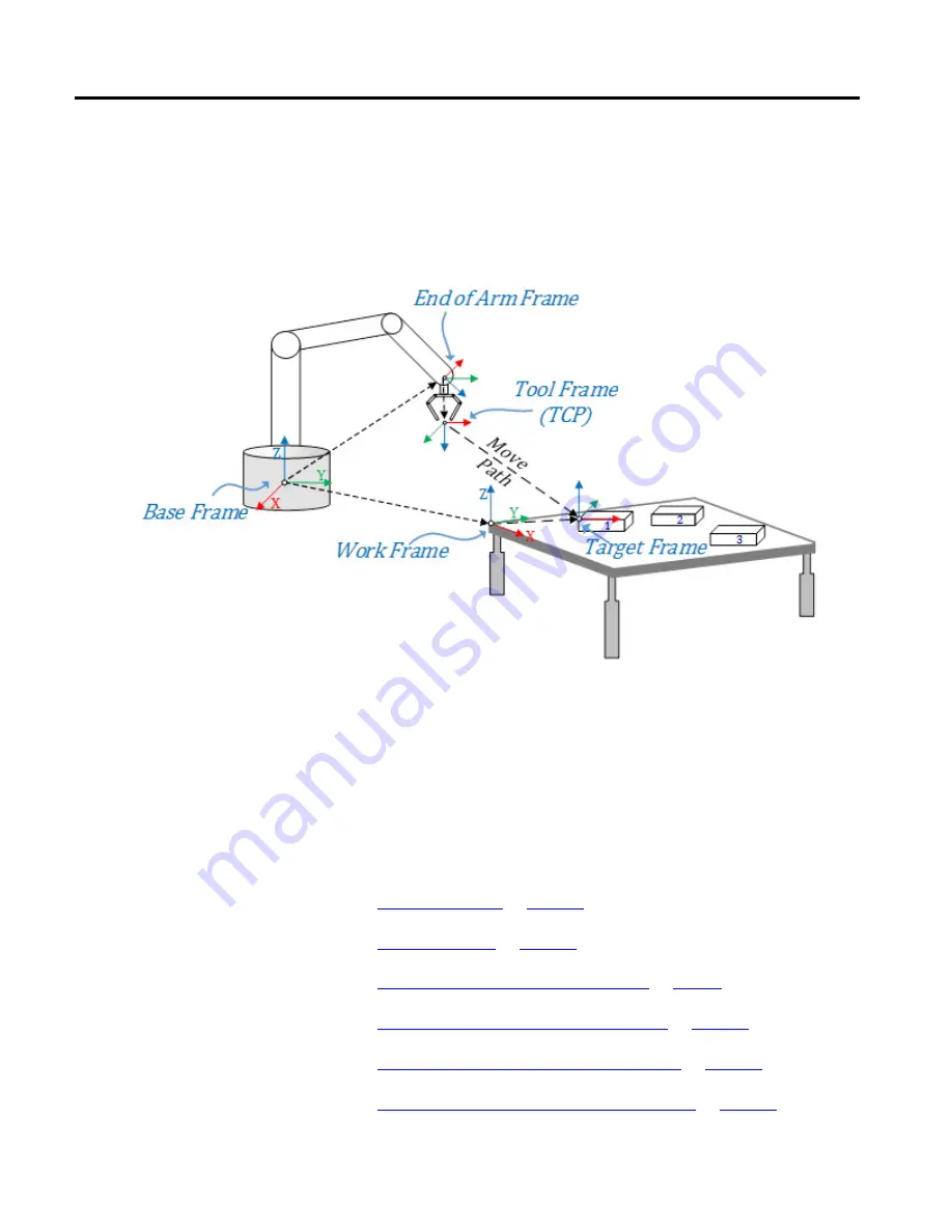
This diagram illustrates simple robot application setup for picking an object from
the table using a gripper tool. Reference frames are established from the base frame
of the robot for the user program. Boxes are placed on a table at known positions
with respect to the table corner, and the table is at a known vector distance or
offset from the robot. Table is set as work frame for this application. A gripper is
attached at the EOA and tool frame is established at the TCP.
In the diagram, the relationship between different frames are shown using arrow
pointing from one origin to another origin of the frame. The arrow direction
indicates which way the frames are defined. The end-of-arm frame and work frame
are defined from the base frame of the robot. The Tool frame is defined from the
end-of-arm frame. All target positions are measured from the work frame using
target frames. The Kinematics planner computes the path for TCP from the
current position to a target position.
See also
Configure a Cartesian Coordinate System
Configure a Delta J1J2J6 Coordinate System
Configure a Delta J1J2J3J6 Coordinate System