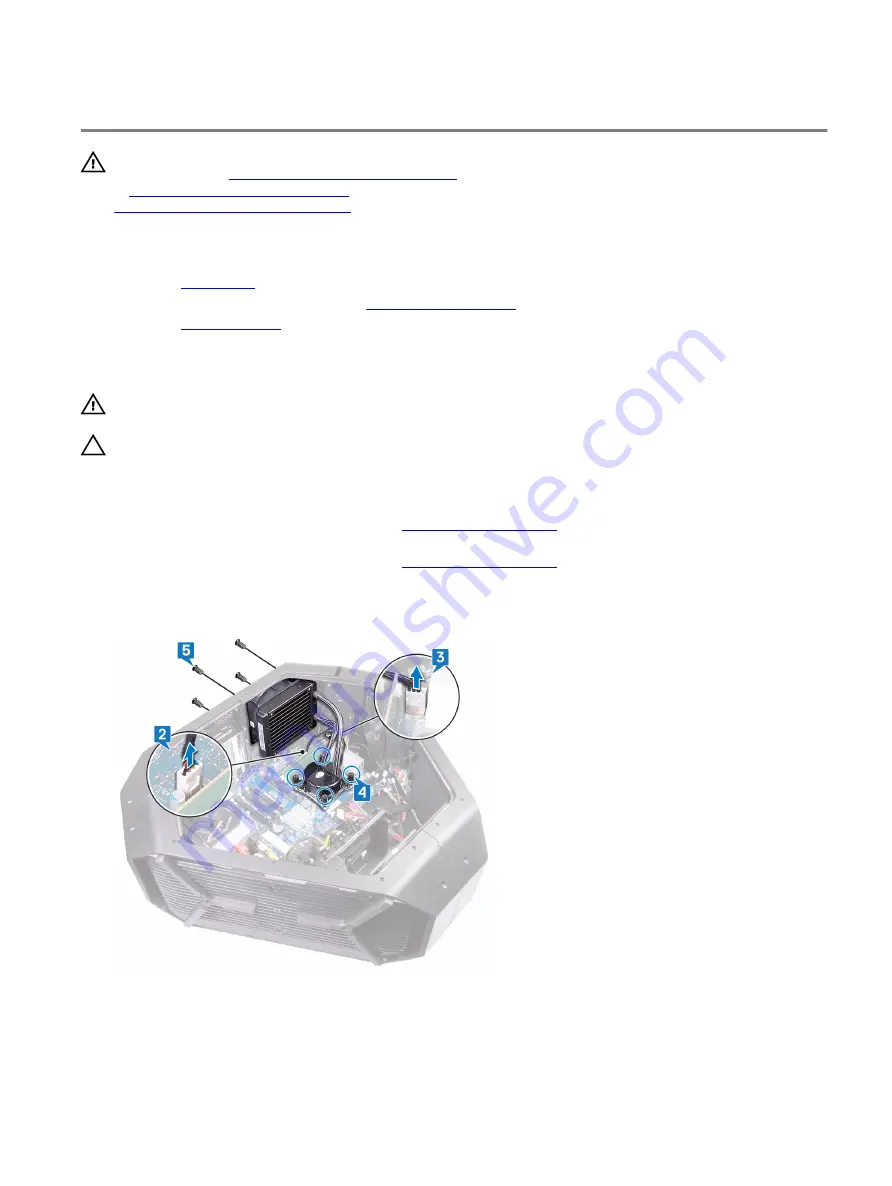
Removing the processor liquid-cooling assembly
WARNING: Before working inside your computer, read the safety information that shipped with your computer and
follow the steps in
Before working inside your computer
. After working inside your computer, follow the instructions
After working inside your computer
. For more safety best practices, see the Regulatory Compliance home page at
www.dell.com/regulatory_compliance
Prerequisites
1
Remove the
2 Remove the left and right side-panels. See “
3 Remove the
Procedure
WARNING: Despite having a plastic shield, the processor liquid-cooling assembly may be very hot during normal
operation. Ensure that it had sufficient time to cool before you touch it.
CAUTION: To ensure maximum cooling for the processor, do not touch the heat transfer areas on the processor
liquid-cooling assembly. The oils in your skin can reduce the heat transfer capability of the thermal grease.
1
Lay the chassis on the right side.
2 Disconnect the processor liquid-cooling assembly fan cable from the system board. For more information on the processor
liquid-cooling assembly fan cable connector, see “
3 Disconnect the processor liquid-cooling assembly fan cable from the system board. For more information on the processor
liquid-cooling assembly fan cable connector, see “
4 In reverse sequential order as indicated on the processor cooling-assembly pump, loosen the captive screws that secure the
processor liquid-cooling assembly pump to the system board.
5 Remove the four screws (#6-32x6) that secure the processor liquid-cooling assembly fan to the chassis.
84
Содержание Area-51 Threadripper Edition R7
Страница 25: ...4 Tilt the computer back to the upright position 25...
Страница 27: ...3 Tilt the computer back to the upright position 27...
Страница 53: ...5 Push the release tab and pry the drive bay heat sensor cable off the chassis 53...
Страница 59: ...7 Lift the graphics card from the graphics card slot 59...
Страница 81: ...5 Push the release tab and pry the front bezel heat sensor cable off the chassis 81...
Страница 97: ...4 Lift the system board assembly out of the chassis 5 Remove the processor 97...
Страница 103: ...9 Press the bottom handle bar to release the securing tab and remove the bottom handle bar 103...
Страница 107: ...2 Replace the stability foot 107...
Страница 109: ...6 Pull the front bezel off the chassis 109...
Страница 119: ...6 Remove the base panel from the chassis Figure 6 Removing the base panel 1 base panel 2 chassis 119...
Страница 122: ...3 Peel the tape that secures the top tron lighting cables to the chassis and lift the top tron lighting cables 122...
Страница 125: ...4 Remove the bottom tron lighting cables from the slot on the chassis 125...
Страница 129: ...12 Pull the antenna cables from the slot on the chassis and remove 129...


