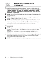
Replacing the Memory Module(s) |
25
3
If you have replaced memory module(s) in connectors DIMM 1 and DIMM 2, go to
Postrequsites.
4
If you have replaced memory module(s) in connectors DIMM 3 and DIMM 4:
a
Align the screw holes on the memory-module cover with the screw holes on the
palm rest assembly.
b
Replace the screws that secure the memory-module cover to the palm rest
assembly.
c
Replace the keyboard. See "Replacing the Keyboard" on page 48.
d
Replace the center control cover. See "Replacing the Center Control Cover" on
page 44.
Postrequsites
1
Replace the compartment door. See "Replacing the Compartment Door" on page 15.
2
Replace the battery pack. See "Replacing the Battery Pack" on page 13.
3
Follow the instructions in "After Working Inside Your Computer" on page 11.
As the computer boots, it detects the additional memory and automatically updates the
system configuration information.
To confirm the amount of memory installed in the computer:
Click
Start
→
Control Panel
→
System and Security
→
System
.
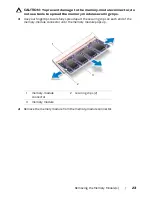
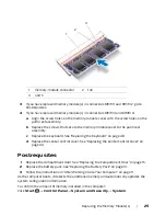
1
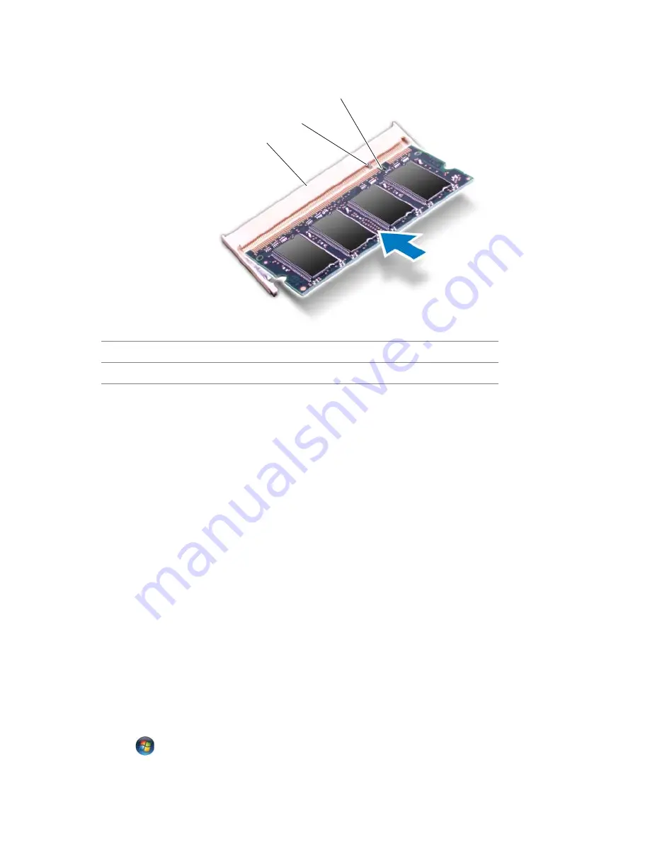
memory-module connector
2
tab
3
notch
1
2
3
Содержание Alienware M17x R4
Страница 1: ...Alienware M17x R4 Owner s Manual Computer model M17x R4 Regulatory model P11E Regulatory type P11E002...
Страница 43: ...Removing the Center Control Cover 43 1 media control keys cable 1...
Страница 59: ...Removing the Display Assembly 59 1 display assembly 2 screws 6 1 2...
Страница 62: ...62 Removing the Status Light Board 1 screws 2 2 status light board 3 status light board cable 1 2 3...
Страница 68: ...68 Removing the Bluetooth Card 1 Bluetooth card cable 2 Bluetooth card 3 screw 1 3 2...
Страница 71: ...Removing the Speakers 71 1 speakers 2 2 screws 4 3 speakers cable 1 2 3...
Страница 75: ...Removing the Optical Drive 75 5 Disconnect the interposer from the optical drive 1 interposer 1...


