background image


17/21 

ALFA IN a.s 

©   


www.alfain.eu

3


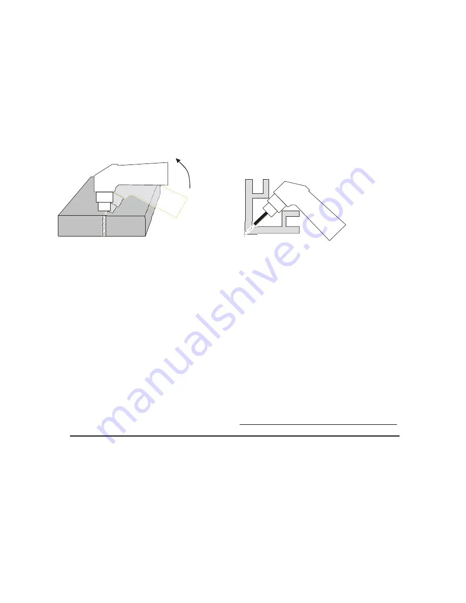
6.   We recommend starting cutting at the edge of the material. If needed to 

start from the centre of the material, or to cut hole into the material, slightly 
tilt the torch head and gradually it straighten into a vertical position so the 
spraying material would not damage the cutting tip (see Figure 5). This 
workflow must always be followed, if the thickness of material is above 
above 3 mm. 

7.  In case of cutting in the corner or around the corner (see Figure 6), use the 

long  electrode and cutting tip. The cutting power while using the Long 
cutting tip is decreased.  


Fig. 5  


                Fig. 6 

7.6  IMPORTANT  RULES 

1.  The pilot arc burning time should be limited only to the time necessary. It 

lowers the wear of the cutting tips and electrodes. 

2.  Never turn off the main switch immediately after finishing cutting but always 

leave time to run cooling cycle to cool down the torch. Immediate turn-off 
only in case of emergency. 

3.  The biggest influence on the cut quality, durability of the nozzles, electrodes 

and the whole torch has compressed air. Ensure correct setting of pressure: 
The pressure during cutting must not fall below 3.5 bar. The air must not 
contain mechanical impurities, oil and water condensate. These 
contaminants reduce the quality of the cut, causing instability and 
extinguishing the arc, and can damage the torch. A source of pressurized 
air must therefore be provided with an effective and reliable filtration, oil 
separator and water condensate trap. Using filters and separators built on 
PEGAS 160 PLASMA as the sole treatment stage air is totally inadequate. 
In cases where the compressor sucks air of high humidity, resulting in the 
need for frequent draining of the pressure tank, it is necessary to include in 
the inlet one more effective as a dirt separator third stage. The captured 
condensate must be discharged every day, and all tailing and pressure 
vessels compressor. 

Ensure a good el. contact of the work lead clamps 

and cutting material.


4.  Check and timely exchange cutting tips and the electrodes. Lifetime of these 

parts is only a few hours of cutting time and is highly dependent on 
compliance with the principles of good cutting. 

Содержание PEGAS 160 PLASMA

Страница 1: ...ALFA IN a s www alfain eu PEGAS 160 PLASMA MANUAL EN 1 PLASMA CUTTING MACHINE PEGAS 160 PLASMA OPERATING MANUAL...

Страница 2: ...DATA 8 5 OPERATOR CONTROLS 9 5 1 FRONT AND REAR PANELS 9 6 ACCESSORIES 10 6 1 PART OF DELIVERY 10 6 2 ON REQUEST 11 7 GETTING STARTED 14 7 1 FIRST STEPS 14 7 2 REQUIREMENTS FOR SOURCE OF COMPRESSED AI...

Страница 3: ...exist when working with this product Read and understand this entire Manual and your employer s safety practices before installing operating or servicing the equipment While the information contained...

Страница 4: ...sy access by the operator to the controls and connectors 11 When the cutting machine is operating all its covers and doors must be closed and well fixed 12 Do not expose the cutting machine to direct...

Страница 5: ...ble materials are removed from the work area to avoid any risk of fire 26 The operator must NEVER cut containers that have previously contained petrol lubricants gas or similar flammable materials eve...

Страница 6: ...ase of a fault developing in the rectifier for example open circuit short circuit or lack of power the permitted values cannot be exceeded The plasma cutting machines of this type can be marked with t...

Страница 7: ...emissions that may interfere with the proper function of cardiac pacemakers hearing aids or other electronic health equipment Persons who work near plasma arc cutting applications should consult thei...

Страница 8: ...current range A V 30 92 0 160 144 0 Open circuit voltage U20 V 345 Cutting current DC 100 I2 A 125 Cutting current DC 60 I2 A 140 Cutting current DC x I2 A 40 160 Max productive cut thickness carbon...

Страница 9: ...etting the working pressure Set the Pressure regulator A13 to working pressure 6 0 bar Setting the optimal air flow for the pilot arc That is set by the manufacturer In case the pilot arc cannot he ig...

Страница 10: ...In case the LED does not go off in 10 minutes call the service A8 LED low air pressure If the pressure is less them 3 5 bar the appliance is blocked A9 Torch central connector A10 Remote control conne...

Страница 11: ...with clamp 3m 35 50 200A 6 2 ON REQUEST Code Description 5481 Circle Cutting Attachment 5482 Cutting Guide 5302 Air filter AT 1000 5303 Air Filter cartridge AT 1000 5304 Set for filter AT 1000 to P 1...

Страница 12: ...12 21 ALFA IN a s www alfain eu3 Fig 3 Torch LT 150 6m Hand...

Страница 13: ...act Extended Tip 1 6 120A LT 150 12 5387 Contact Extended Tip 1 8 150A LT 150 13 5388 Contact nozzle retaining cup LT 150 13 5389 Contact nozzle retaining cup Max Life LT 150 14 5390 Spring Holder pro...

Страница 14: ...personnel 1 Before beginning work is necessary to connect the machine to the mains 2 Check completeness of the mounted cutting torch 3 See the picture below Connect the torch to the connector By means...

Страница 15: ...rigger In the 4 stroke mode press the torch trigger 7 2 REQUIREMENTS FOR SOURCE OF COMPRESSED AIR 1 Delivered air pressure must be max 8 5 bar and min 5 bar 2 Air consumption minimal 220 l min 3 Compr...

Страница 16: ...utting speeds may be reduced to allow slower cutting when following a line or using a template or cutting guide while still producing cuts of excellent quality 4 To achieve a good cutting quality make...

Страница 17: ...ility of the nozzles electrodes and the whole torch has compressed air Ensure correct setting of pressure The pressure during cutting must not fall below 3 5 bar The air must not contain mechanical im...

Страница 18: ...e area of the cutting tip and it would prevent ignition of the pilot arc 7 7 SOURCES OF POOR QUALITY CUTS 7 7 1 Shallow penetration of the cut 1 The cutting speed is too high Make sure the slope of th...

Страница 19: ...egular draining of the condensate traps at least once a day Furthermore visually check the level of pollution of the air filter and if necessary disassemble and cleaned the filter 4 Setting the operat...

Страница 20: ...lease contact your ALFA IN product supplier for the warranty repair procedure 5 ALFA IN warranty will not apply to a Equipment that has been modified by any other party other than ALFA IN s own servic...

Страница 21: ...www alfain eu3 implementation in accordance with national law electric tools that have reached the end of their service life must be collected separately and returned to an environmentally compatible...

Отзывы: