background image

Monitoring Chassis Temperature

Chassis and Power Supplies

page 2-26

OmniSwitch 10K Hardware Users Guide

August 2015

Monitoring Chassis Temperature

The operating temperature of your switch is a critical factor in its overall operability. In order to avoid a 
temperature-related system failure, your switch must always run at a temperature within the specified 
operating temperature range. Refer to the 

page 2-3

 for more information. 

To avoid chassis over-temperature conditions, follow the important chassis airflow recommendations on 

page 2-7

.

Monitoring Chassis Temperature Status

To check the switch’s current temperature status, use the 

show temperature


command. For example:

-> show temperature

Device | Current |  Range  | Danger | Thresh |  Status

-------+---------+---------+--------+--------+-----------------

CMMA       45       15-73      73       68     UNDER THRESHOLD

CMMB       45       15-73      73       68     UNDER THRESHOLD

FABA       46       15-73      73       68     UNDER THRESHOLD

Slot1      43       15-73      73       68     UNDER THRESHOLD

Slot3      43       15-73      73       68     UNDER THRESHOLD

Slot4      43       15-73      73       68     UNDER THRESHOLD

Note: All temperatures are in Celsius.

For more information about this command, see the “Chassis Management and Monitoring Commands” 
chapter in the 

OmniSwitch CLI Reference Guide

.

Temperature Errors

The CMM monitors the chassis ambient air temperature at all times via an onboard sensor. If an over-
temperature condition occurs, there are two different levels of error severity:

Warning threshold has been exceeded

Danger threshold has been exceeded

Содержание OmniSwitch 10K

Страница 1: ...Part No 060310 10 Rev H August 2015 OmniSwitch 10K Hardware Users Guide enterprise alcatel lucent com ...

Страница 2: ... of ALE Holding visit enterprise alcatel lucent com trademarks All other trademarks are the property of their respective owners The information presented is subject to change without notice Neither ALE Holding nor any of its affiliates assumes any responsibility for inaccuracies contained herein July 2015 26801 West Agoura Road Calabasas CA 91301 818 880 3500 FAX 818 880 3505 Service Support Conta...

Страница 3: ...s 1 1 Hardware Redundancy 1 1 Smart Continuous Switching 1 2 Hot Swapping 1 2 Hot Swap Time Guidelines 1 2 Hardware Monitoring 1 3 Automatic Monitoring 1 3 LEDs 1 3 User Driven Monitoring 1 3 Power Checking Sequence 1 3 Installing a New NI into a Running Chassis 1 3 Chapter 2 Chassis and Power Supplies 2 1 OmniSwitch 10K Chassis 2 2 Chassis Slot Numbering 2 4 Mounting the Switch 2 5 Lifting the Ch...

Страница 4: ...ing the Chassis 2 24 Monitoring Chassis Components 2 25 Viewing Chassis Slot Information 2 25 Monitoring Chassis Temperature 2 26 Monitoring Chassis Temperature Status 2 26 Temperature Errors 2 26 Warning Threshold 2 27 Temperature Danger Threshold 2 27 Monitoring Fan Tray Status 2 28 Fan Tray Redundancy 2 28 Structured Cabling 2 29 Chapter 3 Chassis Management and Fabric Modules 3 1 Chassis Manag...

Страница 5: ...dth 3 14 Pinouts 3 15 Chapter 4 Network Interface NI Modules 4 1 In This Chapter 4 1 GNI Modules 4 2 XNI Modules 4 2 QNI Modules 4 2 OS10K GNI C48E Front Panel 4 3 OS10K GNI U48E Front Panel 4 4 OS10K XNI U32S Front Panel 4 5 OS10K XNI U32E Front Panel 4 6 OS10K XNI U16E Front Panel 4 7 OS10K XNI U16L Front Panel 4 8 OS10K QNI U4E Front Panel 4 9 OS10K QNI U8E Front Panel 4 10 Monitoring NI Module...

Страница 6: ...iance A 4 Safety Standards A 4 EMC Standards A 4 Environmental Standards A 5 FCC Class A Part 15 A 5 Canada Class A Statement A 5 JATE A 5 CISPR22 Class A Warning A 6 VCCI A 6 Class A Warning for Taiwan and Other Chinese Markets A 6 Network Cable Installation Warning A 7 Translated Safety Warnings A 7 Chassis Lifting Warning A 7 Blank Panels Warning A 7 Electrical Storm Warning A 7 Installation Wa...

Страница 7: ...tencia de instalación A 12 Advertencia de radiación láser invisible A 12 Advertencia de la batería de litio A 12 Advertencia sobre la tensión de operación A 12 Advertencia sobre la desconexión de la fuente A 12 Advertencia sobre una apropiada conexión a tierra A 13 Leer información importante de seguridad A 13 Advertencia de acceso restringido A 13 Advertencia de pulsera antiestática A 13 Clase de...

Страница 8: ...Contents viii OmniSwitch 10K Hardware Users Guide August 2015 ...

Страница 9: ... to gain knowledge of OmniSwitch 10K hardware will benefit from the material in this guide When Should I Read this Manual Read this guide as soon as you are ready to familiarize yourself with your switch hardware components You should have already stepped through the first login procedures and read the brief hardware overviews in the OmniSwitch 10K Getting Started Guide You should already be famil...

Страница 10: ...MM redundancy Hardware related Command Line Interface CLI commands What is Not in this Manual The descriptive and procedural information in this manual focuses on switch hardware It includes information on some CLI commands that pertain directly to hardware configuration but it is not intended as a software users guide There are several OmniSwitch users guides that focus on switch software configu...

Страница 11: ...itch Management Guide Once you have your switch up and running you will want to begin investigating basic aspects of its hardware and software Information about switch hardware is provided in the OmniSwitch 10K Hardware Guide This guide provide specifications illustrations and descriptions of all hardware components such as chassis power supplies Chassis Management Modules CMMs Network Interface N...

Страница 12: ...PFC ETC and DCBX Anytime The OmniSwitch CLI Reference Guide contains comprehensive information on all CLI commands supported by the switch This guide includes syntax default usage example related CLI command and CLI to MIB variable mapping information for all CLI commands supported by the switch This guide can be consulted anytime during the configuration process to find detailed and specific info...

Страница 13: ...ls included in the base software package Chapters cover Layer 2 information Ethernet and VLAN configuration Layer 3 information routing protocols such as RIP and IPX security options authenticated VLANs Quality of Service QoS link aggregation and server load balancing OmniSwitch AOS Release 7 Advanced Routing Configuration Guide Includes network configuration procedures and descriptive information...

Страница 14: ...rdware replacement through our global network of highly qualified service delivery partners With 24 hour access to Alcatel Lucent s Service and Support web page you ll be able to view and update any case open or closed that you have reported to Alcatel Lucent s technical support open a new case or access helpful release notes technical bulletins and manuals Access additional information on Alcatel...

Страница 15: ...are hardware and software based safeguards that help prevent the loss of data flow in the unlikely event of a subsystem failure In addition some availability features allow users to maintain or replace hardware components without powering off the switch or interrupting switch operations Combined these features provide added resiliency and help ensure that the switch is consistently available for d...

Страница 16: ... will be disabled Hot Swapping Hot swapping refers to the action of adding removing or replacing certain hardware components without powering off your switch and disrupting other components in the chassis This feature greatly facilitates hardware upgrades and maintenance and also allows you to easily replace components in the unlikely event of hardware failure The following hardware components can...

Страница 17: ...he current status of hardware components The user enters show commands that output information to the console Show commands for all the features are detailed in the OmniSwitch CLI Reference Guide Power Checking Sequence The power checking sequence is another built in availability feature This feature helps regulate power in the switch whenever the switch is booted or an NI module is installed in t...

Страница 18: ...OmniSwitch 10K Availability Features OmniSwitch 10K page 1 4 OmniSwitch 10K Hardware Users Guide August 2015 ...

Страница 19: ...e Technical specifications page 2 3 Switch mounting information page 2 5 Power supplies and power supply redundancy page 2 11 Temperature management page 2 25 Chassis fan tray on page 2 28 Monitoring the chassis components via the Command Line Interface CLI page 2 28 Note Detailed information on Chassis Management Modules CMMs Chassis Fabric Modules CFMs and Network Interface NI modules can be fou...

Страница 20: ...work Interface NI modules Additional slots are used for primary and redundant Chassis Management Modules CMMs Chassis Fabric Modules CFMs fan trays and power supplies Item Description A Module Slots Provides eight NI module slots two CMM module slots and two CFM module slots B Fan Trays C Air Intake Vent D Power Supply Slots E Air Exhaust Vent F Chassis Grounding Lug G Power Supply Fan Exhaust Ven...

Страница 21: ...wer Supply Bays 4 Fabric Redundancy 3 1 Ambient Temperature Tmra Operating 0ºC to 45ºC 32ºF to 113ºF Temperature Danger Threshold 73ºC Operating and Storage Humidity 10 to 90 non condensing Chassis Width 19 inches 48 3cm 17 4 inches 44 2cm without rack mount flanges Height 28 inches 71 2 cm or 16 RU Overall Depth 23 5 inches 59 7 cm Chassis Weight empty approx 46 pounds 20 9 kg Chassis Weight full...

Страница 22: ...uide August 2015 Chassis Slot Numbering The term slot refers to the specific position in the chassis where components are installed OmniSwitch 10K slots are laid out as follows OmniSwitch 10K Slot Numbering Slot Component 1 8 NI Slots A B CMMs C D CFMs FAN 1 2 Fan Trays PS 1 4 Power Supplies ...

Страница 23: ...people are required when lifting the chassis Do not move a populated switch chassis Be sure to remove all modules fan trays and power supplies and set them aside before lifting When lifting the chassis use the recessed hand grip provided on the rear panel and the reinforced area immediately under the front air intake plenum Refer to the diagram below for more information Important Due to its weigh...

Страница 24: ...eration of the equipment is not compromised Refer to Airflow Recommendations on page 2 7 for more information Mechanical Loading Mounting of the equipment in the rack should be such that a hazardous condition is not achieved due to uneven loading Circuit Overloading Consideration should be give to the connection of the equipment to the supply circuit and the effect that overloading of circuits cou...

Страница 25: ...lead to switch failure Chassis Top View Note Clearance is not required at the top and bottom of the chassis OmniSwitch 10K fan trays draw air from the intake vents located at the bottom front and left and right sides of the chassis The air is directed up through the chassis module compartment and past the CMM CFM and NI circuit boards Airflow is then exhausted through the vent at the top rear of t...

Страница 26: ...rect route from the air intake vents up through the chassis module compartment and out through the exhaust plenum as intended Instead a portion of the airflow is allowed to escape through the front module compartment of the chassis As a result normal airflow is disrupted and an extra task is placed on the fan trays to cool the chassis Cover panels also provide protection for module processor board...

Страница 27: ...e to its weight and airflow requirements the OmniSwitch 10K cannot be wall mounted To rack mount the switch follow the steps below 1 Mark the holes on the rack where the chassis is to be installed 2 Using two people lift and position the chassis until the rack mount flanges are flush with the rack post Refer to page 2 5 for information on properly lifting the chassis 3 Align the holes in the flang...

Страница 28: ... installed Approximate chassis weights are provided on page 2 3 For a standalone unit use two or more people to move and position the unpopulated chassis upright on the surface where it is to be installed Be sure that adequate clearance has been provided for chassis airflow and that you have placed the chassis within reach of all required AC outlets For recommended airflow allowances refer to page...

Страница 29: ...mation AC Power Supply Front Panel Model OS10K PS 25A Product Compatibility OmniSwitch 10K Input Voltage 90 264 VAC auto ranging Operating Frequency 47 63 Hz Maximum Input Current 16A 118 VAC nominal load Output Power 2500W 180 264 VAC 1200W 90 132 VAC Output Voltage Range 10 8V to 13 2Vdc Output Current 110 VAC 104A 230 VAC 208A Operating Temperature 10 to 70 degrees Celsius operating Humidity 30...

Страница 30: ...ption AC Green Off The power supply has passed diagnostics and is operating normally The power supply is not connected to a power source or has been placed in power saving mode See DC FLT status LED information below DC FLT Dual Color Green Red Output power is OK The power supply has been placed in power saving mode or a power supply failure has been detected ...

Страница 31: ...nput Voltage Range 36VDC to 72VDC Input Frequency 400KHz Output Power 2400W Ambient Temperature 10 to 70 degrees Celsius operating 40 to 85 degrees Celsius non operating Humidity 30 to 95 Relative Humidity Operating 10 to 95 Relative Humidity Storage LED State Description DC INPUT OK Green Off DC input is OK No or very low DC input is detected e g the power supply is not connected to a power sourc...

Страница 32: ... important guidelines listed below be sure to consult manufacturer specifications for the DC power source before starting Connect the power supply to a reliably grounded 48V or 60V SELV source The branch circuit overcurrent protection must be rated 75A Use two 10 AWG copper conductors A readily accessible disconnect device that is suitably approved and rated shall be incorporated in the field wiri...

Страница 33: ...vides basic guidelines Refer to power budget guidelines on page 2 16 for additional details 120V Power Source PS1 Supports basic switch operation PS2 Supports basic switch operation may provide redundancy based on chassis configuration PS3 Supports basic switch operation may provide redundancy based on chassis configuration PS4 Supports basic switch operation may provide redundancy based on chassi...

Страница 34: ...wer before adding a module to verify that the current chassis power supports the change Use the show chassis command to determine available power budget Refer to the table below for component power requirements Refer to the table below for effects of removing power supplies on overall power budget Module being added to chassis Additional watts needed OS10K CMM 81 W OS10K CFM 46 W per CFM added OS1...

Страница 35: ...so for the power supply to seat properly make sure that the handle is in the open horizontal position as shown 2 Slide the power supply back until its connector meets the chassis backplane 3 When the power supply is fully seated rotate the handle 90 degrees to the closed vertical position 4 Tighten the captive screw located at the top left of the power supply s front panel 5 Plug the power cord pr...

Страница 36: ...own and place the cord retainer assembly against the front panel of the power supply 7 Secure the bracket to the bottom rail of the chassis using the captive screw and then route the power cord through the retainer bracket as shown Note Connecting a the power supplies to a power source at this time will boot the chassis ...

Страница 37: ... power cord from its power source 2 Free the power cord from the cord retainer clip and remove the cord retainer assembly from the power supply by loosening the captive screw 3 Unplug the power cord from the power supply socket 4 Loosen the captive screw located at the top left of the power supply s front panel 5 Rotate the handle 90 degrees to the open horizontal position ...

Страница 38: ...ide August 2015 6 Slide the power supply out of the power supply bay Note If you are not replacing the power supply be sure to install a blank cover panel over the empty power supply bay To install a blank cover panel fasten the panel to the bottom rail of the chassis using the captive screw ...

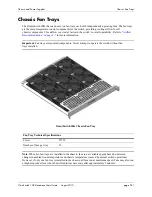
Страница 39: ... on page 2 7 for more information Important Fan trays are required components Never attempt to operate the switch without fan trays installed OmniSwitch 10K Chassis Fan Tray Note When two fan trays are installed in the chassis fans run at variable speeds based on detected changes in ambient room temperature and chassis temperature caused by normal switch operations However if only one fan tray is ...

Страница 40: ...upplies page 2 22 OmniSwitch 10K Hardware Users Guide August 2015 Removing Fan Trays 1 Begin by loosening the two captive screws located at the left and right sides of the tray s front panel 2 Pull the fan tray straight out of the chassis ...

Страница 41: ...015 page 2 23 Installing Fan Trays 1 Insert the tray into the chassis slot and slide it straight back until it meets the chassis backplane connectors 2 When the fan tray is firmly seated in the chassis tighten the two captive screws at the left and right sides of the fan tray s front panel ...

Страница 42: ...hassis These holes use 10 32 screws and are surrounded by a small paint free rectangular area which provides metal to metal contact for a ground connection Use this connector to supplement the ground provided by the AC power cord To do so install a Panduit Grounding Lug type LCD8 10A L using 8AWG copper conductors to the paint free rectangular area Refer to the rear chassis view on page 2 2 for lo...

Страница 43: ...010 OS10 GNI C48 To view more detailed information use the show module long command show module long Module in slot CMM A Model Name OS10 CPM Description CMM Part Number 543212345 Hardware Revision 123 Serial Number 123454321 Manufacture Date Jan 20 2010 FPGA Physical 1 Dec 24 2009 Admin Status POWER ON Operational Status UP Max Power 0 Power Consumption 888 CPU Model Type MPC8572 Motorola MAC Add...

Страница 44: ...ch s current temperature status use the show temperature command For example show temperature Device Current Range Danger Thresh Status CMMA 45 15 73 73 68 UNDER THRESHOLD CMMB 45 15 73 73 68 UNDER THRESHOLD FABA 46 15 73 73 68 UNDER THRESHOLD Slot1 43 15 73 73 68 UNDER THRESHOLD Slot3 43 15 73 73 68 UNDER THRESHOLD Slot4 43 15 73 73 68 UNDER THRESHOLD Note All temperatures are in Celsius For more...

Страница 45: ...anually set to an otherwise common or acceptable ambient temperature for example 55 degrees Centigrade The default warning threshold is 70C This value may be configured using the temp threshold command The current set warning threshold may be viewed using the show temperature command Note Once the ambient air temperature is reduced to below the warning threshold the CMM s TEMP LED automatically re...

Страница 46: ...an 2 Running For more information about this command see the Chassis Management and Monitoring Commands chapter in the OmniSwitch CLI Reference Guide Fan Tray Redundancy In the event that one fan tray quits unexpectedly the remaining fan tray will continue running switch operations are not disrupted Note Fan failure needs to be reported immediately in order to make an RMA unit available and upon r...

Страница 47: ...onnectors cable architectures terminations and polarity are defined The standard is intended to support a range of existing and future applications Deploying equipment for speeds above 10Gbps requires different standards than previous implementa tions and polarity becomes a much more important aspect of the deployment The TIA 568 C standards define various methods for addressing the polarity issue...

Страница 48: ...Monitoring Chassis Temperature Chassis and Power Supplies page 2 30 OmniSwitch 10K Hardware Users Guide August 2015 ...

Страница 49: ...nagement and power management Chassis Fabric Module CFM The Chassis Fabric Module CFM provides expanded switching fabric for the chassis Data passing from one NI module to another passes through the CFM Additional CFMs provide increased switching throughput as well as redundancy CMM and CFM Slot Locations Slot numbers are clearly marked on the OS10K front panel In a non redundant i e single CMM co...

Страница 50: ...e Status LEDs Provides status on hardware software primary and redundant power Refer to CMM CFM LED Status Indicators on page 3 4 for LED status information B Console Port RS 232 console port with an RJ 45 connector Provides access to the CLI for configuration and management C USB Port High speed USB 2 0 port D Ethernet Management Port OS10K CMM Technical Specifications Power 81 W D C B A ...

Страница 51: ...ch 10K Hardware Users Guide August 2015 page 3 3 OS10K CFM Front Panel CFM Front Panel Item Description A Module Status LEDs Provides module status Refer to CMM CFM LED Status Indicators on page 3 4 for LED status information OS10K CFM Technical Specifications Power 46 W A ...

Страница 52: ...lost to all active power supplies while this feature is enabled LED State Description OK1 Green Amber Passed diagnostics Failed diagnostics OK2 Green Amber Operational Transitional state e g downloading code Control Green Green Blinking Amber Amber Blinking CMM Processor is Primary CMM processor is Secondary CMM processor is not functioning correctly CMM processor upgrade in progress Fabric Green ...

Страница 53: ...lled in a chassis the CMM occupying slot A is the primary CMM by default To install an CMM or CFM module follow the steps below 1 Insert the module into the slot along the chassis card guides The component side of the board should face right The module should slide in easily Note Do not force the module into the slot If resistance is encountered make sure the module is aligned properly in the card...

Страница 54: ...simultaneously until the module is firmly seated The bottom lever should overlap the top lever Caution In order to avoid personal injury caused by pinch hazard be sure to keep hands and fingers clear of the area between the extractor levers as they close Caution Pinch Point Hazard To avoid personal injury use thumbs to depress both extractor levers and keep hands and fingers clear of area between ...

Страница 55: ...gement and Fabric Modules Installing CMM and CFM Modules OmniSwitch 10K Hardware Users Guide August 2015 page 3 7 4 Once the module is firmly seated secure the module to the chassis by tightening the captive screws ...

Страница 56: ...ort located on the CMM front panel provides a serial connection to the switch and is required when logging into the switch for the first time By default this R J45 connector provides a DCE console connection Serial Connection Default Settings The factory default settings for the serial connection are as follows baud rate 9600 parity none data bits word size 8 stop bits 1 X ON X OFF enabled ...

Страница 57: ...M failover sequence 1 CMM A installed in the left hand Slot A position is operating in the primary mode CMM B installed in the right hand Slot B position is operating in the secondary mode i e it is functioning as the standby CMM and is ready to take over chassis management functions in the event of a primary CMM failure 2 CMM A fails or is taken offline e g the module is physically removed from t...

Страница 58: ...ore removing or replacing the primary CMM in a redundant configuration verify that the primary and secondary CMM modules are synchronized Otherwise data flow and switch management functions may be interrupted due to incorrect or outdated software when the secondary CMM takes over Refer to CMM Redundancy on page 3 9 and the Managing CMM Directory Content chapter in the Switch Management Guide for d...

Страница 59: ...he Switch Management Guide A CMM reload is essentially a soft boot of the module Note that you can reload only one CMM module at a time the primary and secondary CMMs cannot be reloaded simultaneously Reloading the Primary CMM If the primary CMM is reloaded the secondary CMM automatically takes over primary management functions In other words the secondary CMM becomes the primary CMM as soon as th...

Страница 60: ...s Command Line Interface CLI offers CMM monitoring commands These commands allow you to access general CMM hardware information as well as the current operating status of CMM related components CMM Hardware Information The show cmm and show hardware info commands are used to display general hardware information for the CMM module s installed in the chassis Use the show cmm command to display the f...

Страница 61: ...output table descriptions refer to the OmniSwitch CLI Reference Guide Operating Status of CMM Related Components The CMM contains the switch s temperature sensor and monitors fan operation If the TEMP or FAN LEDs on the CMM s front panel indicate an error you can use the show temperature and show fan commands to access additional status information For information on reading temperature and fan st...

Страница 62: ... boards The following chart outlines performance per port group based on the number of fabric boards installed NI Type Port Group One Fabric Board Two Fabric Boards Three Fabric Boards Four Fabric Boards OS10K XNI U32S OS10K XNI U32E Four groups of eight 10Gb ports Not Supported Any five ports per group operate at wire rate All ports operate at wire rate All ports operate at wire rate OS10K GNI U4...

Страница 63: ...t and Fabric Modules Pinouts OmniSwitch 10K Hardware Users Guide August 2015 page 3 15 Pinouts RJ 45 Console Port Connector Pinout Pin Number Signals as DTE Console Port 1 NC 2 NC 3 RXD 4 Ground 5 Ground 6 TXD 7 NC 8 NC ...

Страница 64: ...Pinouts Chassis Management and Fabric Modules page 3 16 OmniSwitch 10K Hardware Users Guide August 2015 ...

Страница 65: ...le for the OmniSwitch 10K Procedures using Command Line Interface CLI commands to manage and monitor NI modules are also provided Specifications descriptions and procedures in this chapter include Specifications and descriptions of GNI modules on page 4 2 Specifications and descriptions of XNI modules on page 4 2 Specifications and descriptions of QNI modules on page 4 2 Procedures for monitoring ...

Страница 66: ...eiver connectors Refer to page 4 6 for information on this module OS10K XNI U16E Provides 16 SFP transceiver connectors Refer to page 4 7 for information on this module OS10K XNI U16L Provides 16 SFP transceiver connectors Refer to page 4 8 for information on this module This is a Lite module restricting 8 ports to 1G speed but can be upgraded to 16 10G ports QNI Modules OmniSwitch 10K 40 Gigabit ...

Страница 67: ...Front Panel Item Description A Ethernet Ports 48 auto sensing auto negotiating and individually configurable as 10BaseT 100BaseTX or 1000BaseT B Port LEDs Provides port link status Refer to Monitoring NI Modules on page 4 11 for LED status information OS10K GNI C48E Technical Specifications Number of Ports 48 Maximum frame size 9216 bytes Power 152 W A B ...

Страница 68: ... A SFP Ports 48 SFP connectors for supported transceivers B Port LEDs Provides port link status Refer to Monitoring NI Modules on page 4 11 for LED status infor mation OS10K GNI U48E Technical Specifications Number of SFP transceiver ports 48 Maximum frame size 9216 bytes SFP Transceivers Refer to the OmniSwitch 10K Transceivers Guide for transceivers specifications Power 154 W B A ...

Страница 69: ...scription A SFP Ports 32 SFP connectors for supported transceivers B Port LEDs Provides port link status Refer to Monitoring NI Modules on page 4 11 for LED status information OS10K XNI U32S Technical Specifications Number of SFP ports 32 Maximum frame size 9216 bytes SFP Transceivers Refer to the OmniSwitch Transceivers Guide for transceivers specifications Power 432 W B A ...

Страница 70: ...scription A SFP Ports 32 SFP connectors for supported transceivers B Port LEDs Provides port link status Refer to Monitoring NI Modules on page 4 11 for LED status information OS10K XNI U32E Technical Specifications Number of SFP ports 32 Maximum frame size 9216 bytes SFP Transceivers Refer to the OmniSwitch Transceivers Guide for transceivers specifications Power 424 W B A ...

Страница 71: ...scription A SFP Ports 16 SFP connectors for supported transceivers B Port LEDs Provides port link status Refer to Monitoring NI Modules on page 4 11 for LED status information OS10K XNI U16E Technical Specifications Number of SFP ports 16 Maximum frame size 9216 bytes SFP Transceivers Refer to the OmniSwitch Transceivers Guide for transceivers specifications Power 225 W B A ...

Страница 72: ...ame functionality as an OS10K XNI U16E 16 10G ports with the U16L upgrade license Item Description A SFP Ports 16 SFP connectors for supported transceivers B Port LEDs Provides port link status Refer to Monitoring NI Modules on page 4 11 for LED status information OS10K XNI U16L Technical Specifications Number of SFP ports 161 Maximum frame size 9216 bytes SFP Transceivers Refer to the OmniSwitch ...

Страница 73: ...ription A QSFP Ports 4 QSFP connectors for supported transceivers B Port LEDs Provides port link status Refer to Monitoring NI Modules on page 4 11 for LED status information OS10K QNI U4E Technical Specifications Number of QSFP ports 4 Maximum frame size 9216 bytes SFP Transceivers Refer to the OmniSwitch Transceivers Guide for transceivers specifications Power 218 W B A ...

Страница 74: ...cription A SFP Ports 8 QSFP connectors for supported transceivers B Port LEDs Provides port link status Refer to Monitoring NI Modules on page 4 11 for LED status information OS10K QNI U8E Technical Specifications Number of QSFP ports 8 Maximum frame size 9216 bytes SFP Transceivers Refer to the OmniSwitch Transceivers Guide for transceivers specifications Power 396 W B A ...

Страница 75: ...g 3 Module in slot 3 Model Name OS10 GNI C48 Description 10 1000 RJ45 Part Number 543212345 Hardware Revision 123 Serial Number 123454321 Manufacture Date Jan 20 2010 FPGA Physical 1 007 Daughter FPGA Physical 1 002 Daughter FPGA Physical 2 002 Admin Status POWER ON Operational Status UP Max Power 250 Power Consumption 200 CPU Model Type Motorola MPC8540 ADS MAC Address 00 d0 95 01 03 01 ASIC Phys...

Страница 76: ... proper procedures to eliminate electrostatic discharge ESD from your person and the surrounding area before installing chassis components Caution Equipment Damage Hazard When removing modules from the chassis use one hand to support the rear of the module as shown Failure to support the rear of the module may cause it to fall and strike the backplane connectors resulting in permanent damage to th...

Страница 77: ...To remove an NI module follow the steps below 1 Loosen the module s two captive screws 2 Simultaneously pull the two module lock levers one on top of the module and one on the bottom until the module disengages from the chassis 3 Slide the module out of the chassis Warning Use caution when removing modules as some components may be hot ...

Страница 78: ... If any resistance is encountered make sure the module is aligned properly in the card guides 2 When the module is nearly seated in the slot be sure that the two extractor levers one on top of the module and one on the bottom are open approximately 90 degrees This allows the notch on each extractor lever to grasp the rail on the chassis 3 Once the notches have grasped the rail press both extractor...

Страница 79: ...ugust 2015 page 4 15 Pinouts 10 100 Mbps Ethernet Port RJ 45 Pinout Gigabit Ethernet Port RJ 45 Pinout Pin Number Description 1 RX 2 RX 3 TX 4 not used 5 not used 6 TX 7 not used 8 not used Pin Number Description 1 BI_DB 2 BI_DB 3 BI_DA 4 BI_DD 5 BI_DD 6 BI_DA 7 BI_DC 8 BI_DC ...

Страница 80: ...s This provides both better performance as well as better repeatability You will always see a variance in transceiver power due to connector alignment good jumper cables help reduce this variance They continue to mate well after many insertions and removals Premium grade jumper use premium connectors that maintain their mechanical integrity up to and beyond 2000 insertion cycles For better repeata...

Страница 81: ...th attenuated when performing loop back testing or testing between two pieces of equipment Too much optical power launched into the receiver will cause saturation and result in system failure If you are using single mode fiber and you do not know the power output of the laser it is always best to use a 10 dB attenuator when testing Using the wrong type of attenuator will introduce problems most no...

Страница 82: ...Handling Fiber and Fiber Optic Connectors Network Interface NI Modules page 4 18 OmniSwitch 10K Hardware Users Guide August 2015 ...

Страница 83: ...füllt die wesentlichen Anforderungen und sonstigen Bestimmungen der Richtlinien 2004 108 EG EMV Richtlinie 2006 95 EG Niederspannungsrichtlinie 91 263 EWG Telekommunikationsendeinrichtungen falls zutreffend 1999 5 EG Funkanlagen und Telekommunika tionsendeinrichtungen falls zutreffend Español Este equipo cumple los requisitos esenciales y otras disposiciones de las directivas 2004 108 CE EMC 2006 ...

Страница 84: ...st one of all homogeneous materials in the parts is above the relevant threshold of the SJ T11363 2006 standard 对销售之日的所售产品 本表显示 阿尔卡特朗讯公司供应链的电子信息产品可能包含这些物质 注意 在所售产 品中可能会也可能不会含有所有所列的部件 This table shows where these substances may be found in the supply chain of Alcatel Lucent electronic information products as of the date of sale of the enclosed product Note that some of the component types listed ab...

Страница 85: ... page A 3 Products are packaged using one or more of the following packaging materials California Proposition 65 Warning WARNING This product contains chemicals known to the State of California to cause cancer and birth defects or other reproductive harm Corrugated Cardboard Corrugated Fiberboard Low Density Polyethylene CB FB ...

Страница 86: ...g unshielded UTP cables Safety Standards UL 60950 1 2nd Edition CAN CSA C22 2 No 60950 1 07 2nd Edition EN 60950 1 with Amendment II IEC 60950 1 2nd Edition AS NZS TS 001 and 60950 Australia UL AR Argentina TUV UL GS Mark Germany NOM 019 SCFI Mexico EN 60825 1 Laser EN 60825 2 Laser CDRH Laser CB Certification per IEC 60950 1 Second Edition EMC Standards FCC Part 15 CFR 47 Class A ICES 003 Class A...

Страница 87: ...pment It is suggested that the user use only shielded and grounded cables to ensure compliance with FCC Rules If this equipment does cause interference to radio or television reception the user is encouraged to try to correct the interference by one or more of the following measures Reorient the receiving antenna Relocate the equipment with respect to the receiver Move the equipment away from the ...

Страница 88: ... Class A product based on the standard of the Voluntary Control Council for Interference by Information Technology Equipment VCCI If this equipment is used in a domestic environment radio disturbance may arise When such trouble occurs the user may be required to take corrective actions Class A Warning for Taiwan and Other Chinese Markets This is a Class A Information Product When used in a residen...

Страница 89: ... power supply bays at all times Français Les caches blancs remplissent trois fonctions importantes ils évitent tout risque de choc électrique à l intérieur du châssis ils font barrage aux interférences électromagnétiques susceptibles d altérer le fonctionnement des autres équipements et ils dirigent le flux d air de refroidissement dans le châssis Il est vivement recommandé de vérifier que tous le...

Страница 90: ...é il est recommandé de ne pas regarder fixement l intérieur de ces ouvertures Installez les caches connecteurs prévus à cet effet Deutsch Die Laser strahlen an der Blendenöffnung unsichtbares Licht ab wenn keine Glasfaserkabel angeschlossen sind Blicken Sie nicht in die Öffnungen und installieren Sie unverzüglich die Abdeckungen über den Glasfaseranschlüssen Español Debido a que la apertura del pu...

Страница 91: ...Warning To avoid shock hazard The power cord must be connected to a properly wired and earth receptacle Any equipment to which this product will attached must also be connected to properly wired receptacles Français Pour éviter tout risque de choc électrique Ne jamais rendre inopérant le conducteur de masse ni utiliser l équipement sans un conducteur de masse adéquatement installé En cas de doute ...

Страница 92: ...de Deutsch Der Getting Started Guide welcher diese Anlage beiliegt enthält wichtige Sicherheitsinformationen über die sie sich beim Arbeiten mit den Hardwareeinheiten bewußt sein sollten Sie sollten diese Hinweise lesen bevor sie installieren reparieren oder die Anlage verwenden Español La Getting Started Guide que acompañó este equipo contiene información importante de seguridad sobre la cual ust...

Страница 93: ... Weil elektrostatische Aufladung ESD Teile der Anlage beschädigen könnten müssen sie sich selbst erden bevor sie mit der Hardware Installation beginnen Zu diesem Zweck stellt Alcatel Lucent ein Erdungsarmband und eine Erdungsöse an der oberen rechten Seite des Chassis zur Verfügung Um eine sichere Erdungsfunktion des Erdungsarmbandes sicherzustellen müssen die Netzteile installiert und mit dem Sch...

Страница 94: ...rtencia de radiación láser invisible Los lasers emiten radiación invisible de la apertura abierta cuando no se conecta ningún cable de fibra óptica Al quitar los cables no mire fijamente en las aberturas abiertas Además instale las cubiertas protectoras de la abertura a las salidas de la fibra sin el cable conectado Advertencia de la batería de litio Hay un peligro de la explosión si la batería de...

Страница 95: ...ue restrinja el acceso Una ubicación con acceso restringido es una donde está seguro y limitado el acceso al personal de servicio que tiene un clave especial u otros medios de la seguridad Advertencia de pulsera antiestática Debido a que la descarga electrostática ESD puede dañar componentes del interruptor usted debe conectarse a tierra correctamente antes de continuar con la instalación del equi...

Страница 96: ...Instrucciones de seguridad en español Regulatory Compliance and Safety Information page A 14 OmniSwitch 10K Hardware Users Guide August 2015 ...

Отзывы: