3.Control Systems
3
–1
Manual control panels are come into service
as standard with the generator set to control
operating conditions and status of the generator
set. Optionally, an electronic remote control
module may also be provided according to the
requirements of the user.
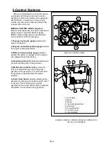
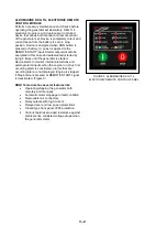
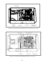
MANUAL CONTROL PANEL (Figure 2)
Manual control panel has an engine oil pressure
gauge, engine coolant temperature gauge,
Battery charge-voltage gauge, operating time
clock and other control components.
1 ) Engine oil pressure gauge
indicates the
engine oil pressure.
2 ) Engine coolant temperature gauge
indicate
the engine coolant temperature.
3 ) Battery charge-voltage gauge
indicates
whether the battery is charged from the engine
and voltage status of the battery.
4 ) Operating time clock
indicates total amount
of hours operating time of the generator.
5 ) Malfunction indicator lamp
is turned by
reason of faults that may occur during the
operation of the generator. It is turned off when
the generator is operated after the fault is
repaired.
6 ) Start / Stop Switch
provides starting of the
generator by pressing on start/stop switch which
is placed on the control panel to use the
generator set manually. When switch is pressed
off position, it is provided to stop generator.
1 ) Terminals
2 ) Relay
3 ) Relay
4 ) Connecting terminal
5 ) Idle Card
6 ) Circuit Breaker
7 ) 12 V DC Fuse
8 ) AC Breaker
MANUAL CONTROL PANEL
FIGURE 2. MANUAL CONTROL PANEL & CONDUIT BOX
- MS, MG,TG,TS MODELS
Содержание MG 309
Страница 4: ......


